Do you have a question about the GF ER 52-1 and is the answer not in the manual?
Explains the meaning of danger, warning, and caution symbols and their implications.
Defines additional symbols used for notes and action calls in the manual.
Provides information on obtaining related technical documents from Georg Fischer.
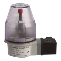
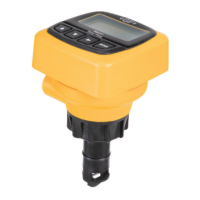
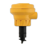
Specifies the intended application and dimensions for the Electrical Position Indicator.
Details general safety guidelines, personnel qualifications, and documentation requirements.
Outlines precautions for protecting the product from environmental factors during transport and storage.
Illustrates the physical components of the ER 52 and ER 53 models with a labeled diagram.
Explains how the position indicator functions with the DIASTAR actuator system.
Presents technical specifications including switch types and switching capacities for ER 52 and ER 53.
Step-by-step guide for installing the position indicator on a basic diaphragm valve.
Instructions for mounting the position indicator on a diaphragm valve equipped with a stroke limiter.
Procedure for adjusting the cams to correctly indicate the valve's open and closed positions.
Details on connecting the position indicator via the unit plug for different functions.
Provides schematic diagrams for electrical connections of various position indicator types.
Instructions for proper separation and disposal of product materials according to regulations.
Manufacturer's declaration of compliance with relevant EC directives for the product.
| Brand | GF |
|---|---|
| Model | ER 52-1 |
| Category | Measuring Instruments |
| Language | English |