EasyManua.ls Logo

GF signet 2551 User Manual

GF signet 2551
20 pages
To Next Page IconTo Next Page
Page #1 background imageLoading...
Page #1 background image
3-2551.090-1 Rev. M 04/15
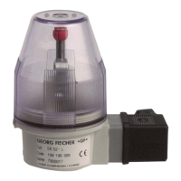
Signet 2551 Display Magmeter
English
The 2551 Magmeter measures the ow rate in a full pipe by monitoring the voltage
produced when the (conductive) uid moves through a magnetic eld. Output
options include a traditional frequency signal, a serial data (Digital (S
3
L)) output,
and a 4 to 20 mA output.
The 2551 Magmeter is available in three sizes that will accommodate pipes from
½ inch through 36 inch diameters.
Select from three different material combinations to match the Magmeter to the
application requirements.
Operating Instructions
Description
Table of Contents
Warranty Information .............................................................................. 2
Product Registration ............................................................................... 2
Safety Information .................................................................................. 2
Chemical Compatibility ........................................................................... 2
Dimensions ............................................................................................. 2
Speci cations ......................................................................................... 3
Installation .............................................................................................. 4
Pipe Fittings ........................................................................................ 4
Selecting a Location............................................................................ 4
Overview Magmeter Display................................................................... 5
Wiring ..................................................................................................... 5
Mirror Relay 1 Output.......................................................................... 5
Frequency Output ............................................................................... 5
4 to 20 mA Output ............................................................................... 6
Wiring to other Manufacturer's Instruments ........................................ 6
Wiring to Signet Flow Instruments ...................................................... 6
Wiring Relays ...................................................................................... 7
Application Notes: Relay Wiring ...................................................... 7
Navigating the Menus ............................................................................. 8
Keypad Functions ............................................................................... 8
Security Code ..................................................................................... 8
View Menu .............................................................................................. 9
Resetting the Resettable Totalizer ...................................................... 9
Setup Menu .......................................................................................... 10
Averaging and Sensitivity ...................................................................11
Bi-Directional Flow ............................................................................ 12
Calibration Data: K-Factors.......................................................... 12-13
Calibration Menu ............................................................................... 14
Volume Method of Calibration ........................................................... 14
Rate Method of Calibration ............................................................... 14
Relay Menus......................................................................................... 15
Pulse Relay Mode ............................................................................. 15
Total Relay Mode .............................................................................. 15
High, Low, or Window Relay Modes ................................................. 16
Test Menu ............................................................................................. 17
Options Menu ....................................................................................... 17
Output Modes ................................................................................... 17
Grounding ............................................................................................. 18
Maintenance ......................................................................................... 18
Troubleshooting .................................................................................... 19
Ordering Information............................................................................. 20
*3-2551.090-1*
• English
• Deutsch
• Français
• Español
• Italiano
• Português

Other manuals for GF signet 2551

Questions and Answers:

GF signet 2551 Specifications

General IconGeneral
BrandGF
Modelsignet 2551
CategoryMeasuring Instruments
LanguageEnglish

Summary

Product Overview

Product Description

Measures flow rate using magnetic field; offers frequency, serial data, and 4-20mA output.

Material Options

Available in three material combinations to match application requirements.

Product Information and Safety

Warranty and Registration

Details warranty terms, repair procedures, and product registration steps.

Safety Precautions and Warnings

General safety steps, hazard symbols, PPE, and tool usage guidance.

Chemical Compatibility Guidance

Advises on compatibility of materials with aggressive substances to prevent failure.

Physical Dimensions

Provides physical dimensions of the magmeter and insertion depths for different pipe sizes.

Technical Specifications

General and Wetted Material Specs

Details pipe size, flow range, linearity, repeatability, and wetted materials used.

Environmental and Power Requirements

Specifies enclosure, operating conditions, and power input requirements.

Output and Relay Specifications

Details 4-20mA, Frequency, S³L outputs, and relay types, ratings, and modes.

Standards and Approvals

Lists certifications such as CE, UL/CUL, NSF, RoHS, and ISO standards.

Installation and Location Selection

Pipe Fittings Overview

Lists available installation fittings and their descriptions for controlling electrode position.

Optimal Location Criteria

Requirements for full pipe, turbulent flow, air pockets, and conduit port orientation.

Straight Pipe Installation

Illustrates required straight pipe lengths upstream of the sensor for accurate measurement.

Flow Direction and Air Bubble Avoidance

Explains how traps and upward flow can affect air bubble exposure and measurement.

Display and Wiring Overview

Magmeter Display and Ports

Describes the dual-sided electronics module, conduit ports, and LED indicators.

Directional Flow Indication

Explains the sensor's directional arrow for forward flow indication and reverse flow display.

Wiring to Mirror Relay 1 Output

Explains how to configure an Open Collector output via the OPTIONS menu for Relay 1.

Wiring to Frequency Output

Details programming the OPTIONS menu for open collector frequency output and AUX PWR connection.

Wiring Configurations

4 to 20 mA Output Wiring

Explains passive 4-20mA output, external loop power, factory calibration, and spanning.

Connecting to Signet Instruments

Wiring diagrams for connecting to 9900 Transmitter and 8900 Controller.

Wiring to Non-Signet Instruments

Details wiring for open collector output to non-Signet instruments requiring a pull-up resistor.

Relay Wiring Details

Mechanical and Solid State Relays

Describes mechanical and solid state relays, their ratings, and applications.

Auxiliary Power for Relays

Explains the need for auxiliary power for relays and display backlighting, and its isolation.

Relay Terminal Legend

Defines terminal designations: NO (Normally Open), NC (Normally Closed), C (Common).

Relay Wiring Application Notes

Advises on using RC filter for inductive loads to prevent arcing and relay damage.

Navigating the Magmeter Interface

Understanding the Display

Describes the default display showing flow rate and resettable totalizer.

Menu Structure Overview

Lists the seven main menus for accessing calibration and programming features.

Accessing Menus

Explains two methods to access menus: scrolling to "Enter Menu" or holding ENTER.

Keypad Functions and Security

Explains keypad operations and the function of the four-digit security code.

Viewing Data and Resetting Totalizer

View Menu Functionality

Displays basic information like flow rate, totalizer, current output, and relay states.

Resettable Totalizer Reset Procedure

Step-by-step instructions for resetting the resettable totalizer, including security code use.

Setup Menu Configuration

K-Factor and Pipe Size Settings

Setting the K-Factor based on pipe size and units for accurate flow measurement.

Flow Units and Totalizer Configuration

Setting display units, timebase, totalizer factor, and units.

Output Span and Cutoff Settings

Setting the flow rates for 4-20mA output and the minimum flow rate cutoff.

Averaging and Sensitivity Adjustment

Adjusting averaging time and sensitivity for optimal flow rate response.

Optimizing Flow Rate Response

Understanding Averaging Function

Explains how averaging time smooths flow rate display and output response.

Understanding Sensitivity Function

Describes how sensitivity overrides averaging for quick response to flow surges.

Combined Averaging and Sensitivity Effects

Illustrates how averaging and sensitivity settings affect flow rate display over time.

Bi-Directional Flow and K-Factors

Bi-Directional Flow Operation

Explains flow direction indication, totalizer behavior, and output scaling for reverse flow.

K-Factor Tables (Polypropylene, PVDF, PVC)

Provides K-Factor values for various pipe sizes and fittings made of Polypropylene, PVDF, and PVC.

K-Factor Tables (Continued)

K-Factor Tables (Steel, Bronze, Copper, Iron)

Continues K-Factor tables for Steel, Bronze, Copper, and Iron fittings.

Calibration Procedures

Calibration Introduction and Needs

Explains how K-Factors account for non-ideal flow conditions and custom calibration.

Volume Method Calibration

Step-by-step guide to calibrating using a known volume of fluid.

Rate Method Calibration

Method for calibrating against a reference flow meter, useful for large pipes.

Relay Mode Configuration

Pulse Relay Mode Operation

Programming a relay to activate for a fixed period based on fluid volume.

Total Relay Mode Operation

Programming a relay to activate when the resettable totalizer reaches a specific value.

Advanced Relay Modes

High, Low, and Window Relay Modes

Setting relays for High, Low, or Window modes based on flow rate setpoints.

Relay Setpoint and Delay Settings

Configuring flow rate setpoints, hysteresis, and time delays for relay activation.

Test and Options Menus

Test Menu Functionality

Simple method to verify system operation by testing output signals and relays.

Options Menu Settings

Configuring language, security code, contrast, reset lock, noise rejection, and decimals.

Output Mode Selection

Selecting output modes like Frequency, Frequency ÷ 10, Mirror Relay 1, or S³L Digital.

Grounding and Maintenance

Electrical Grounding Procedures

Recommendations for proper grounding to eliminate electrical noise and ensure measurement accuracy.

Magmeter Maintenance Guidelines

Basic maintenance, including cleaning electrodes with soft cloth and mild detergent.

Environmental Recommendations

Notes on environmental safety and proper disposal of electronic components.

Troubleshooting Guide

Output and Signal Issues

Troubleshooting erratic output, zero flow issues, and incorrect signal readings.

Display, Power, and Error Messages

Diagnosing blank displays, no backlighting, or error messages like "Error Not Saved".

LED Indicators and Pipe Status

Explains LED states and how the magmeter indicates empty pipe conditions.

Ordering Information

Frequency and Digital Output Models

Part numbers, codes, and descriptions for frequency/digital output models.

4 to 20 mA Output Models

Part numbers, codes, and descriptions for 4 to 20 mA output models.

Replacement Parts and Accessories

Lists available replacement parts like O-rings, retaining nut kits, and RC filter kits.

Related product manuals