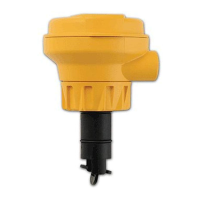
Signet 2551 Magmeter
SAFETY INSTRUCTIONS
1. Depressurize and vent system prior to installation or removal.
2. Confi rm chemical compatibility before use.
3. Do not exceed maximum temperature/pressure specifi cations.
4. Wear safety goggles or faceshield during installation/service.
5. Do not alter product construction.
*3-2551.090-1*
3-2551.090-1 Rev. G 10/08 English
1.0 Description
The 2551 Magmeter measures the fl ow rate in a full pipe by monitoring the voltage produced when the (conductive) fl uid moves through
a magnetic fi eld.
Output options include a traditional frequency signal, a serial data (digital) output, and a 4-20 mA output.
The 2551 Magmeter is available in three sizes that will accommodate pipes from ½ inch through 12 inch diameters.
Select from four different material combinations to match the magmeter to the application requirements.
English
1.0 Description 1
2.0 Specifi cations 2
3.0 Installation: Pipe fi ttings 3
3.1 Location of Fitting 3
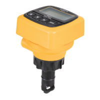
4.0 Overview of 2551 Display versions 4
5.0 Wiring 5
5.1 Basic Wiring 5
5.2 Wiring: Mirror Relay 1 output 5
5.3 2551 and other manufacturer's instruments 5
5.4 Wiring to Signet Flow Instruments 6
5.5 Wiring Relays 7
6.0 View Menu 8
6.1 Resetting the Resetable Totalizer 8
6.2 Navigating the Menus 9
6.3 Keypad Functions 9
6.4 Security Code 9
7.0 Setup Menu 10
7.1 Averaging and Sensitivity 11
7.2 Bi-Directional Flow 12
7.3 Calibration Data 12
8.0 Calibration Menu 14
8.1 Volume method of calibration 14
8.2 Rate method of calibration 14
9.0 Relay Menus 15
9.1 Pulse Relay mode 15
9.2 Total Relay mode 15
9.3 High, Low, or Window Relay modes 16
10.0 Test Menu 17
11.0 Options Menu 17
11.1 Output Modes 17
12.0 Technical Information 18
12.1 Grounding 18
12.2 Maintenance 19
12.3 Troubleshooting 19
13.0 Ordering Information 20
FAILURE TO FOLLOW THESE INSTRUCTIONS MAY RESULT
IN THE SENSOR BEING EJECTED FROM THE PIPE!
• DO NOT USE ANY TOOLS ON THE RETAINING CAP.
HAND TIGHTEN ONLY.
• THE O-RINGS CAN BE LIGHTLY LUBRICATED TO
FACILITATE INSERTION INTO THE PIPE FITTING. DO
NOT USE PETROLEUM-BASED LUBRICANTS!
• DO NOT USE THREAD SEALANT OR LUBRICANTS ON
THE RETAINING CAP OR ON THE PLASTIC FITTING
THREADS.
• IF LEAKING IS OBSERVED FROM THE RETAINING CAP,
IT INDICATES DEFECTIVE OR WORN O-RINGS ON THE SENSOR. DO NOT ATTEMPT TO CORRECT BY FURTHER
TIGHTENING.
The O-rings can be lightly
lubricated to facilitate insertion
into the pipe fitting.
DO NOT USE petroleum-based
lubricants on O-rings!
DO NOT USE thread sealant
or lubricants on the fitting
threads.
Flow
Do not use any tools to
tighten the yellow retaining cap.
DO NOT USE thread sealant or
lubricants on retaining cap!
Contents
WARNING!