10
INSTALLATION INSTRUCTIONS
FOR POLYPROPYLENE PIPE FROM DURAVENT
(Polypro single wall gas vent system):
PolyPro
®
Make sure that all horizontal runs have a minimum
rise of 1/4” inch per foot (21 mm/m) of run. Follow
instruction of the vent pipe manufacturer for proper
vent support.
Pipe Assembly
WARNING
ALWAYS read and abide by all safety messages
printed on the primer, cleaner and cement contain-
ers. Primer, cleaner and cements are extremely
flammable. DO NOT store these products near heat,
sparks or flames. They are harmful or fatal if swal-
lowed. Their vapours are also harmful. They may
irritate eyes and can be absorbed through the skin.
Failure to follow these instructions can result in prop-
erty damage, personal injury, or death.
PVC & CPVC VENT SYSTEM:
1) Adjust the vent pipe length to properly fit the vent sys-
tem adaptor on the blower assembly outlet.
2) Cut pipe ends squarely, removing all burrs and dirt.
3) Dry fit the pipe/fitting to be connected to make sure
they fit properly.
4) Clean the pipe/fitting with the proper primer or cleaner.
5) Apply a thin coat of cement to the fitting, avoiding
puddling inside.
6) Apply a liberal coat of cement to the vent pipe, leav-
ing no voids.
7) QUICKLY assemble parts while cement is fluid! If
you wait too long, re-coat pipe/fitting.
8) Push the vent pipe completely into the coupling,
turning as it goes until it bottoms out.
9) Hold pipe and fitting together for thirty (30) seconds. Then
carefully clean off any excess material with a cloth. Allow
connections a sufficient time to cure before disturbing.
10) Loosen the upper hose clamp on the rubber transition
fitting and fully insert the CPVC pipe of the vent system
adaptor (1” [2.5 cm] deep). Do not apply cement to the
rubber transition fitting.
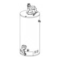
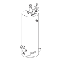
Figure 12
1) Vent pipe
2) Power vent assembly
3) Union
4) Cold water
manual shut-off valve
5) Cold water inlet
6) Expansion tank
7) Temperature
and pressure-relief valve
8) Overflow tube
9) Drain valve
10) Combustion
air intake holes
11) Drain pan
12) Free-flowing floor drain
13) Sight glass
14) Resettable Thermal Switch
15) Outer access door
16) Inner access door
17) Flammable vapour sensor
18) Cap
19) Drip leg (Sediment trap)
20) Gas supply
manual shut-off valve
21) Union
22) Gas control valve
23) Rating plate
24) Dip-tube
25) 12’ Power cord (3.86 m)
26) Hot water outlet
27) Union
28) Flame sensor
29) Ignitor
30) Burner orifice
31) Burner
2
5
6
3
4
7
8
24
9
10
11
16
14
15
13
12
21
17
18
20
19
22
23
25
27
26
31
29
28
30
1
Minimum Slope
1/4”/foot (21mm/m)