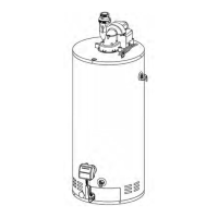
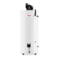
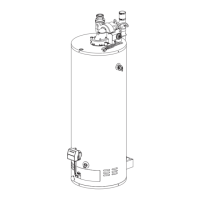
9
POLYPROPYLENE PIPE FROM DURAVENT
(Polypro single wall gas vent system):
PolyPro
®
Use special appliance adapter from DuraVent and insert
into the vent system adaptor on the outlet of the blower
assembly. Refer to the Table 3 and Figure 11 below for
proper part number from DuraVent. On the three (3) inch
(7.6 cm) vent pipe, an increaser is necessary. Make sure
to use the Appliance Adapter clamp to connect the PolyPro
Appliance Adaptor to the Vent System Adaptor and to
tighten both hose clamps on the Appliance Adapter Clamp
to ensure the connection is secure.
Table 3 — DuraVent™
Appliance
adapter
Increaser
Appliance
adapter
clamp
2-inch (5.1 cm) pipe
2PPS-AD N/A PPS-PAC
3-inch (7.6 cm) pipe
2PPS-AD 2PPS-X3 PPS-PAC
Through-the-Wall Venting Installation
Cut or drill a hole through the exterior wall, slightly larger
than the diameter of the vent pipe selected. The larger
hole will allow for final alignment with the water heater.
Extend a section of the pipe through the hole to the
outside and attach the terminating elbow to the exte-
rior end of the pipe. Connect and secure all piping and
elbows from the power venter to the wall. When the
installation is completed, the vent terminal must be at
two (2) inches (5.1 cm) from the exterior surface of the
wall (see Figure 8). Make sure that all piping is prop-
erly braced. If the venting will pass through an enclosed
area, make sure to leave at least one (1) inch (2.5 cm)
clearance around the piping for air circulation.
FOR PVC AND CPVC PIPING:
Make sure that all horizontal runs have a minimum
rise of 1/4 inch per foot (21 mm/m) of run (see Figure
8). Horizontal runs of vent pipe must be supported
every three (3) feet (91 cm).
FOR POLYPROPYLENE PIPE FROM CENTROTHERM
(Innoflue single wall vent system):
InnoFlue
®
Make sure that all horizontal runs have a minimum
rise of 5/8” inch per foot (56 mm/m) of run. Follow
instruction of the vent pipe manufacturer for proper
vent support.
FOR POLYPROPYLENE PIPE FROM DURAVENT
(Polypro single wall gas vent system):
PolyPro
®
Make sure that all horizontal runs have a minimum
rise of 1/4” inch per foot (21 mm/m) of run. Follow
instruction of the vent pipe manufacturer for proper
vent support.
Through-the-Roof Venting Installation
Cut or drill a hole through the roof and ceiling, slightly
larger than the diameter of the vent pipe selected. The
larger hole will allow for the final alignment with the
water heater. Construct the vent terminal assembly.
Extend a section of pipe through the hole in the roof
to the outside and attach the terminal assembly to the
exterior end of the pipe. Connect and secure all piping
and elbows from the power venter to the roof. When
the installation is completed, the vent terminal must be
a minimum of eighteen (18) inches (45.7 cm) from the
exterior surface of the roof (see Figure 8). Make sure
that all piping is properly braced. If the venting will pass
through an enclosed area, make sure to leave at least
one (1) inch (2.5 cm) clearance around the piping for
air circulation.
FOR PVC AND CPVC PIPING:
Make sure that all horizontal runs have a minimum
rise of 1/4 inch per foot (21 mm/m) of run (see Figure
8). Horizontal runs of vent pipe must be supported
every three (3) feet (91 cm) and vertical runs of vent
pipe must be supported every five (5) feet (1.5 m).
FOR POLYPROPYLENE PIPE FROM CENTROTHERM
(Innoflue single wall vent system):
InnoFlue
®
Make sure that all horizontal runs have a minimum
rise of 5/8” inch per foot (56 mm/m) of run. Follow
instruction of the vent pipe manufacturer for proper
vent support.
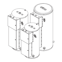
INSTALLATION INSTRUCTIONS
Appliance adaptor
2” venting
3” venting
Increaser
Figure 10 — InnoFlue
®
Centrotherm
2” venting
3” venting
Appliance adaptor
Vent System Adaptor
Appliance
Adaptor
Clamp
Appliance
Adaptor Clamp
Increaser
Figure 11 — PolyPro
®
DuraVent