10
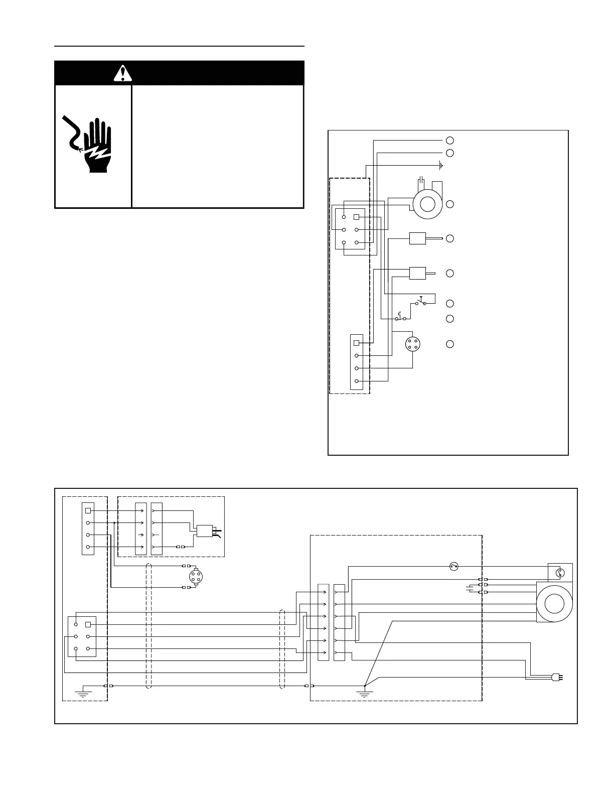
ELECTRICAL REQUIREMENTS & WIRING DIAGRAM
Failure to do so can result in
death or electrical shock.
Replace all parts and panels
before operating.
Disconnect power before
servicing.
Electric Shock Hazard
WARNING
Before plugging in the water heater, always make sure:
• The voltage and frequency correspond to that
specified on the water heater wiring diagram.
• The electrical outlet has the proper overload fuse or
breaker protection.
1. The unit must be connected to a 120VAC power
supply. A dedicated circuit is preferred. Do not use a
GFI outlet.
2. The water heater must be properly grounded.
3. This water heater is a polarity sensitive appliance and
will not operate if the power supply polarity is reversed.
Note: Always reference the wiring diagram for the correct
electrical connections.
After making all electrical connections, completely fill the
tank with water and check all connections for leaks. Open
the nearest hot-water faucet and let it run for 3 minutes to
purge the water lines of air and sediment and to ensure
complete filling of the tank. The electrical power may then
be turned on. Verify proper operation after servicing. See
also
“Installation Checklist”.
120Vac/60Hz Wall Plug/
PRISE ÉLECTRIQUE
120 VCA/60 Hz
FLAMMABLE VAPOUR
SENSOR/
DÉTECTEUR DE
VAPEURS INFLAMMABLES
IGNITER - FLAME ROD
ASSEMBLY/
ALLUMEUR-DÉTECTEUR
DE
FLAMMES
PRESSURE SWITCH/
PRESSOSTAT
CAPACITOR/
CONDENSATEUR
JUNCTION BOX/
BLOC DE JONCTION
WHITE-RODGERS GAS VALVE/
COMMANDE DU
GAZ WHITE-RODGERS
HIGH LIMIT
SWITCH/
LIMITEUR DE
TEMPÉRATURE
BK
YE
GY
OR
BU
BU
GN
GY
WH
WH
WH
WH
YE
OR
BN
BLACK SMOOTH - LINE/
NOIR UNI - LIGNE
BLACK RIBBED - NEUTRAL/
TRAIT NOIR - NEUTRE
BLACK MIDDLE - GND/
NOIR CENTRE - MALT
GN
BK
BK
YE
BK
WH
GN
BU
IF WIRING HAS TO BE REPLACED IN THE FIELD, USE ONLY TYPE TEW 105°C WIRE.
SI LE FILAGE ELECTRIQUE DOIT REMPLACE SUR PLACE,
UTILISER SEULEMENT LE FILAGE DE TYPE TEW 105° C.
1
4
P
2
3
1
2
3
4
J
1
4
5
6
P
2
3
1
2
3
4
5
6
J
2
3
4
5
6
1
1
2
4
3
Figure 8.
CAUTION:
LABEL ALL WIRES PRIOR TO DISCONNECTION WHEN
SERVICING CONTROLS. WIRING ERRORS CAN
CAUSE IMPROPER AND DANGEROUS OPERATION.
VERIFY PROPER OPERATION AFTER SERVICING.
POWER VENT WIRING SCHEMATIC.
Elecrical Connections for White-Rodgers Valve
N
Hot Surface Igniter / Allumeur
High Limit Switch /
Limiteur De Température
Capacitor / Condensateur
L1
Earth Gnd / Malt
Pressure Switch /
Pressostat
Blower /
Soufflerie
Flame Sensor /
Détecteur De Flammes
Flammable Vapour Sensor /
Détecteur De Vapeurs
Inflammables
Circled numbers indicate sequence of operation.
Le numéros encerclés indiquent
la séquence d'opération.
If wiring has to be replaced in the field, use only type TEW 105°C wire.
Si le filage electrique doit être remplacé sur place, utiliser
seulement le filage de type TEW 105°C.
Electrical rating 120V 12A 60Hz. / Admissibles electriques 120V 12A 60Hz.
4
6
1
5
3
2
7
1
1
4
3
2
2
3
4
5
6
1
Figure 9.
 Loading...