25
Concentric Vent Termination Installation
A concentric vent termination kit (see Table 4) may be
used for vertical or horizontal terminations. Figure 26
illustrates the concentric vent kit for a horizontal (side
wall) installation. To prevent rain water from entering the
exhaust outlet, slope the vent kit at a downward pitch
of 6mm (1/4”) per 1.5m (5’) away from the inside wall.
Ensure the combustion air intake location is above the
anticipated snow level.
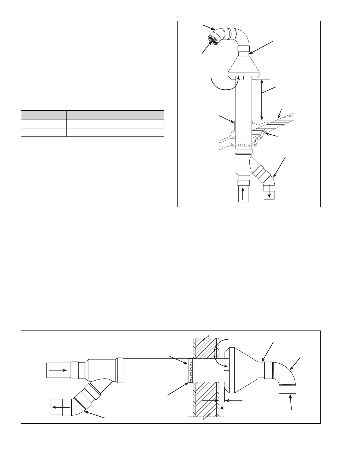
Figure 27 illustrates the concentric
vent termination kit in a vertical (roof) installation. Ensure
the combustion air intake location is above the anticipated
snow level.
VENT DIA. P/N
2” 100112869
3” 100111100
Table 4.
STRAP (FIELD
SUPPLIED)
COMBUSTION
AIR
COMBUSTION
AIR
ORIENTATION OF EXHAUST PIPING AND COMBUSTION AIR PIPING RELATIVE
TO EACH OTHER MAY BE VERTICAL (AS SHOWN) OR AT ANY OTHER ANGLE
TO SUIT THE INSTALLATION.
ELBOW (FIELD
SUPPLIED)
SLOPE 6mm (1/4”)
OVER 1.5m (5’)
VENT SCREEN
INSIDE
EXHAUST
25mm (1”) MAXIMUM
WALL
90° ELBOW
(SEE LOCAL
CODES)
PIPE NIPPLE (USE
WITH ELBOW)
Figure 26.
STRAP (FIELD
SUPPLIED)
COMBUSTION
AIR
COMBUSTION
AIR
ABOVE SNOW
ACCUMULATION
LEVEL OR 450mm
(18”) MIN. ABOVE
ROOF.
ELBOW (FIELD
SUPPLIED)
VENT SCREEN
INSIDE
EXHAUST
ROOF
45° ELBOW
(SEE LOCAL
CODES)
FLASHING (FIELD
SUPPLIED)
PIPE NIPPLE
Figure 27.
 Loading...