8
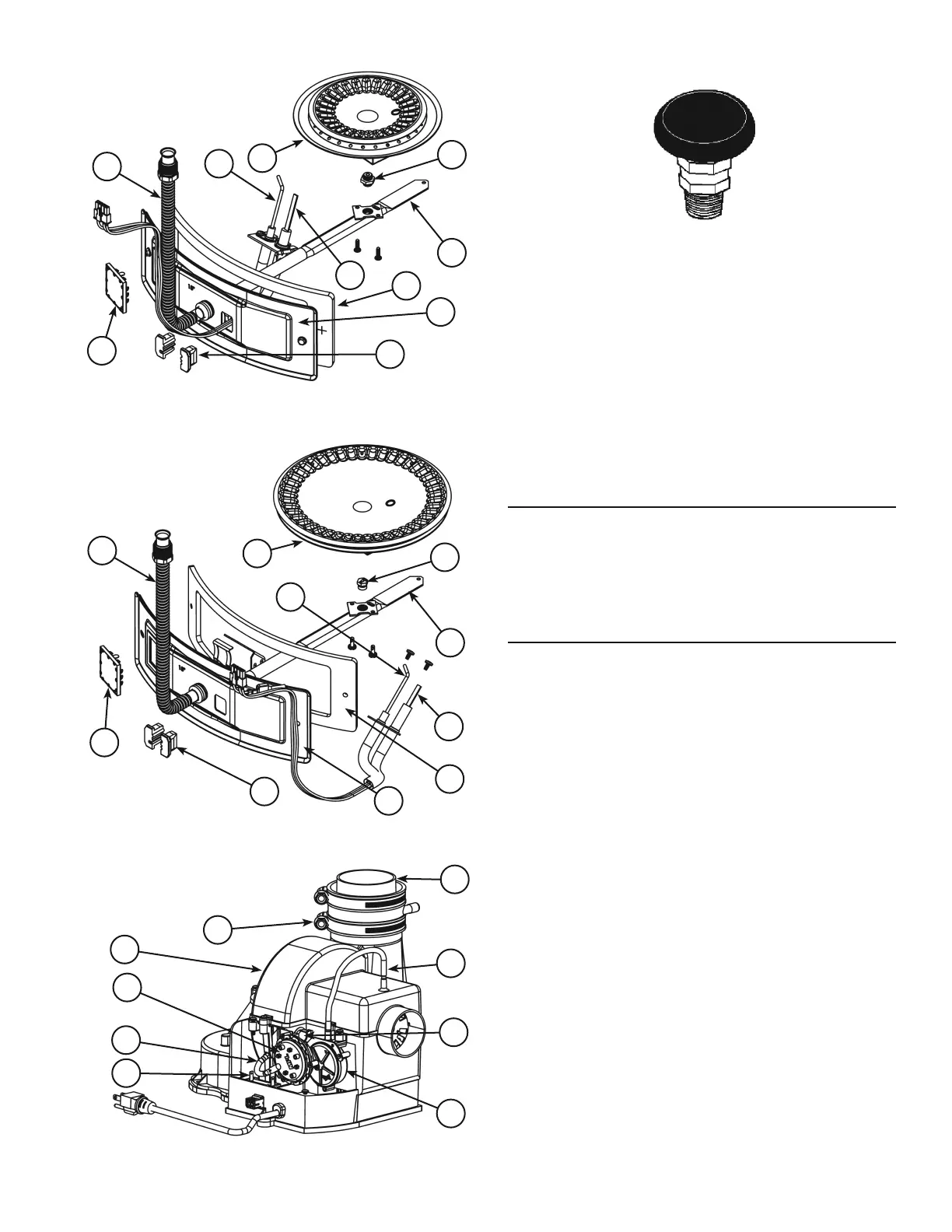
Natural gas and Propane main
burner with igniter assembly
for 40k and 45k Btu/hr models
(item
15 in Figure 1) †.
41
43
39
36
38
40
37
35
18
42
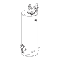
Figure 3.
Natural gas and Propane
(LP) main burner with
igniter assembly for 58k,
62k, 72k and 76k Btu/
hr models (item
15 in
Figure 1) †.
41
43
39
36
38
40
37
35
42
18
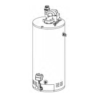
Figure 4.
28
29
44
46
30
49
Shown with
Junction Box Cover
removed for clarity.
45
48
47
Figure 5.
Vacuum relief valve
install per local
codes (not supplied
with heater).
Figure 6.
Notes:
* Items not supplied with the water heater.
** The side recirculation loop connections may not be
used as the primary water inlet and outlet connections.
See
“Combo Heating Inlet And Outlet Side Taps”
below.
*** Caution harness has 120 VAC In operation.
**** See
“Vent Pipe Installation” for more information.
† Propane (LP) models have Left-hand threads.
REPLACEMENT PARTS AND DELIMING PRODUCTS
Replacement parts and recommended delimer may be
ordered through authorized servicers or distributors. When
ordering parts, provide complete model and serial numbers
(see rating plate), quantity and name of part desired.
Standard hardware items may be purchased locally.
COMBO HEATING INLET AND OUTLET SIDE TAPS
Models equipped with Combo Heating capabilities have
the two side plumbing taps plugged (item 7 and item 10 in
Figure 1. If the heater is to be installed in a Combo Heating
application, these plugs must be removed.
 Loading...