7
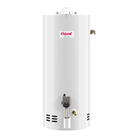
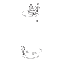
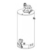
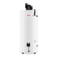
TYPICAL INSTALLATION
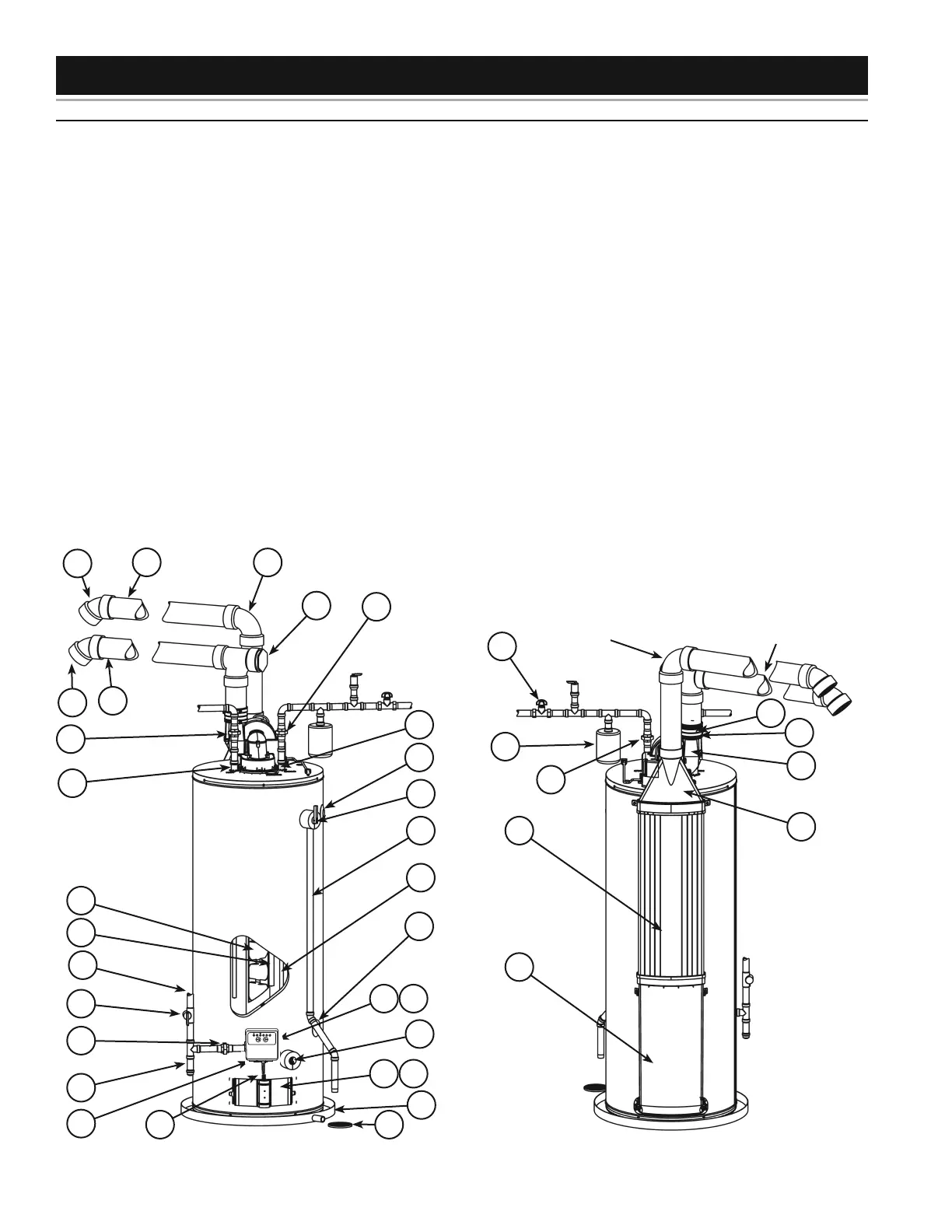
GET TO KNOW YOUR WATER HEATER - GAS MODELS (LIST REFERENCING FIGURES 1-5)
1 Termination Elbow with Vent Screen
2 *Vent Pipe
3 *Vent Pipe Elbow (long radius)
4 Sound Suppressor (Optional)
5 *Union (Di-electric water
connection)
6 Cold-Water Inlet Nipple/Diptube
7 **Combo Heating System Supply
Outlet (Optional)
8 T&P Valve
9 * Discharge Pipe
10 **Combo Heating System Return
Inlet (Optional)
11 Gas Control Valve/Thermostat
(Resideo)
12 Gas Valve Electronic Control
Module And Cover (Resideo)
13 Drain Valve
14 Outer Gas Door
15 Manifold Door Assembly (behind
outer door) (see Figure 3 &
Figure 4)
16 *Metal Drain Pan
17 *Floor Drain
18 Flexible Manifold Tube (see
Figure 3 & Figure 4)
19 ***Control Harness
20 *Sediment Trap
21 *Ground Joint Union (gas
connection)
22 *Main Manual Gas Shut-off Valve
23 *Gas Supply*
24 Anode (under cap)
25 Baffle Assembly
26 Hot-Water Outlet Nipple/Anode
27 *Inlet Water Shut-off Valve
28 ****Rubber Coupling (see Figure 5)
29 Gear Clamp (see Figure 5)
30 ***Blower with Power Cord (see
Figure 5)
31 Air Duct Adapter
32 Air Inlet Snorkel
33 Air Duct
34 *Thermal Expansion Tank (see
“Closed Water Systems” and
“Thermal Expansion” sections)
35 Flame Sensor Rod (see Figure 3 &
Figure 4)
36 Sheet Metal Burner (see
Figure 3 &
Figure 4)
37 Gas Orifice (see Figure 3 &
Figure 4)
38 Gas Manifold (see Figure 3 &
Figure 4)
39 Hot-Surface Igniter (see Figure 3 &
Figure 4)
40 Manifold Door Gasket (see Figure 3
& Figure 4)
41 Manifold Door (see Figure 3 &
Figure 4)
42 Two Piece Grommet With Clip (see
Figure 3 & Figure 4)
43 Viewport (see Figure 3 & Figure 4)
44 Air Tubing (Intake) (see Figure 5)
45 Blower High Limit Switch (see
Figure 5)
46 Intake Air Pressure Switch (NC)
(inside box) (see Figure 5)
47 Capacitor (see Figure 5)
48 Air Tubing (Exhaust) (see Figure 5)
49 Exhaust Air Pressure Switch (NO)
(inside box) (see Figure 5)
*, **, ***, **** see notes on following
page
Rear View
27
34
5
29
30
33
28
AIR INLET
PIPING
EXHAUST OUTLET
PIPING
32
31
Front View
1
2
3
4
5
8
6
9
13
16
1718
20
21
22
23
25
5
26
1
2
11 12
14 15
24
6
19
7
10
Figure 1. Figure 2.
VACATION
WARM
COOLER HOTTER
VERY
HOT
A
BC
 Loading...