2
• Questo prodotto è stato collaudato in GI.BI.DI. verificando la perfetta corrispondenza delle caratteristiche
alle direttive vigenti.
• La GI.BI.DI. S.r.l. si riserva la facoltà di modificare i dati tecnici senza avviso, in funzione dell'evoluzione
del prodotto.
• This product has been tested in Gi.Bi.Di. verifying the perfect correspondence of the characteristics to the
current directive.
• Gi.Bi.Di. S.r.l. reserves the right to modify the technical data without prior notice depending on the product
development.
LEGGERE ATTENTAMENTE QUESTO MANUALE PRIMA DI PROCEDERE ALL’INSTALLAZIONE.
I
UK
3
1
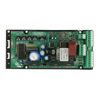
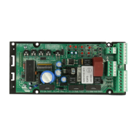
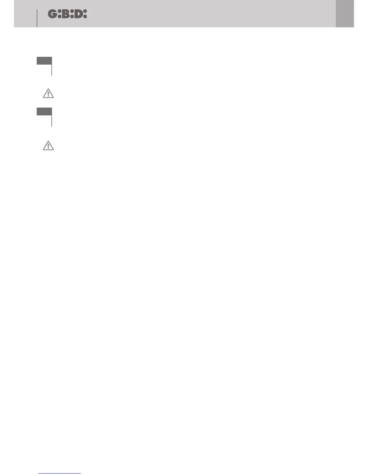
SCHEMA ELETTRICO / ELECTRICAL CONNECTION
BA24 BA24
PLEASE READ CAREFULLY THIS MANUAL BEFORE PROCEEDING WITH THE INSTALLATION.
GND
ANT
JP1
24Vcc 10W MAX
LAMP
LAMP
SW1 SW2 SW3 SW4
LCD1
24Vcc 3W MAX
+24Vdc
+24Vdc
PED
START
FCA M1
STOP
FCA M2
FCC M2
PHOTO 2
RISERVA
COM
FCC M1
JP3
DL1
DL2
DL3
DL4
DL5
DL6
DL7
DL8
DL9
DL10
DL11
M2
MOTOR
CLOSE
MOTOR
OPEN
M1
MOTOR
CLOSE
MOTOR
OPEN
JP4
COM EL
EL1
EL2
GND
SPIA
24Vdc
SEC
JP5
JP2
RL1 RL2 RL3 RL5
RL4
RL6 RL7
RL8 RL9
F1
F3
BA24
D1
CF1
CF2
F2
LED STATUS
ON
OFF
AC
AC
+ SK
- SK
(AS05020)
CB24
~ 230Vac
24Vac
24Vac
PHOTO 1
COSTA
PED (NO)
FCA M1 (NC)
STOP (NC)
FCA M2 (NC)
FCC M2 (NC)
PHOTO 2 (NC)
PHOTO 1 (NC)
COSTA (NC)
COM
FCC M1 (NC)
START (NO)
JP3
RISERVA (NC)
JP6
RX
1 2 3 4 5 6 7 8 9 10 11 12 13 14 15 16 17
18 19 20 21 22 23 24 25 26 27 28 29
30 31
18 19 20 21 22 23 24 25 26 27 28 29

 Loading...