46
UK
47
UK
BA24 BA24
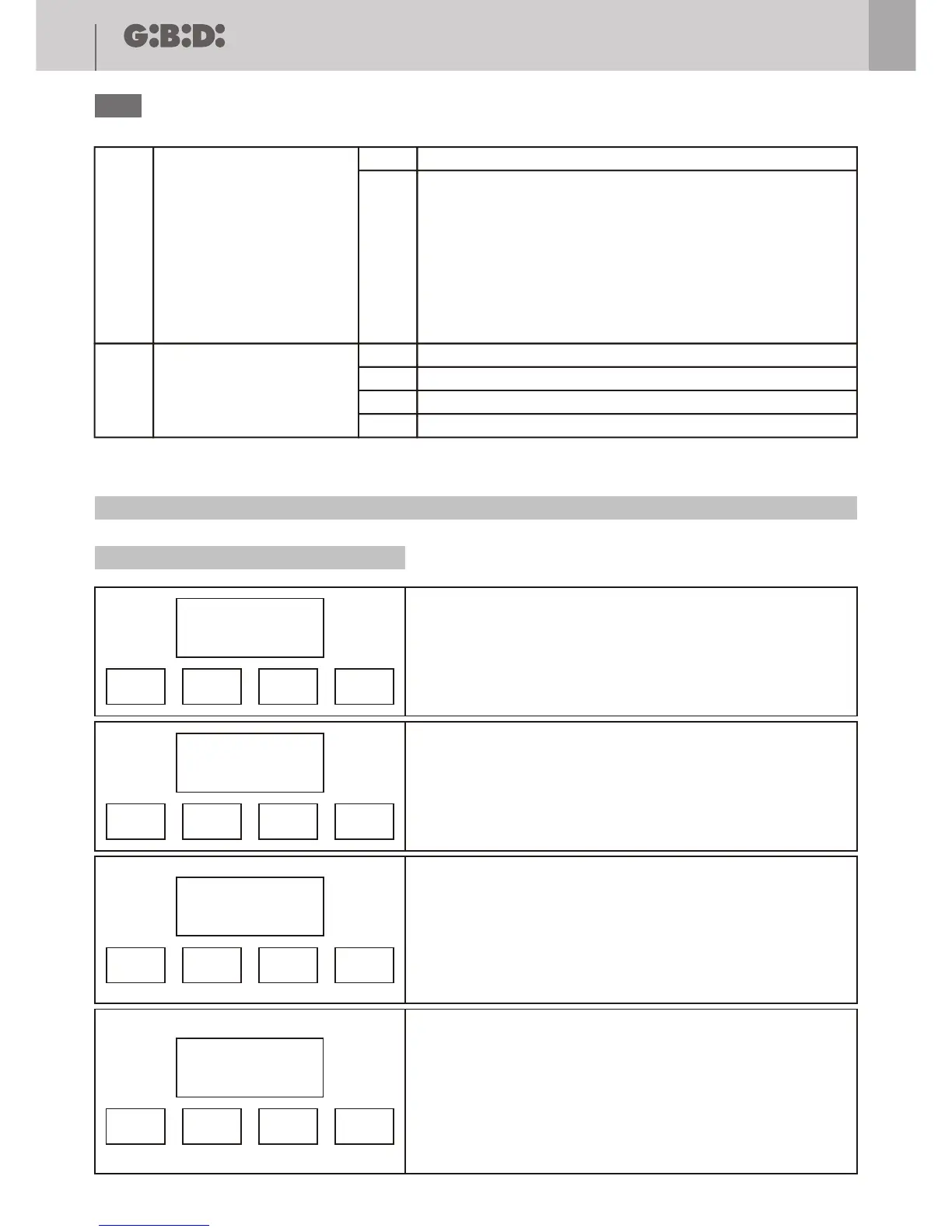
MENU F: FORCE AND SPEED ADJUSTEMENT
A C F H E
ESC-
OK +
F 1
ESC-
OK +
When the display shows the main menus (letters A C F H E or just
some of them depending on which password has been used to access
programming) let the letter F blink by moving to the right or to the left
with the buttons + or –
Once the letter F blinks confirm with the OK button.
By means of + or – buttons you can select the submenus (F1, F2, F3)...
The digits on the lcd are fixed to show that is no possible any
modification.
The button ESC lets you to go to the upper level (menus A, C, F, , E).
With OK button you enter the selected menu and the value set is shown.
0 0 0 5
ESC-
OK +
0 0 0 5
ESC-
OK +
The digits on the lcd are still fixed to shown that is not possible any
modification.
The buttons + and – are irrelevant
The ESC button return to the upper level
With OK button you enter the selected menu and the digits begin
blinking.
A digit of the lcd blinks (depending on the menu the blinking digit could
be different).
With + and – buttons you can modify the value of the blinking digit.
The ESC button moves the blinking digit to the left until the first digit
you can modify.
With OK you confirm and go to the next step.
The next digit starts blinking
With + and – buttons you can modify the value of the blinking digit.
The ESC button moves the blinking digit to the left untill the first digit
you can modify.
With OK you confirm and go to the next step.
0 0 0 5
ESC-
OK +
F 2
ESC-
OK +
Appears again menu F2.
With ESC return to the upper level (menu A, C, F, H, E)
Menu Function Description
Adjusts the thrust of motor 1.
0001 = minimum force
0010 = maximum force
Adjusts the thrust of motor 2.
0001 = minimum force
0010 = maximum force
Adjusts the thrust of motor 1 during deceleration phase.
0001 = minimum force
0010 = maximum force
Adjusts the thrust of motor 2 during deceleration phase.
0001 = minimum force
0010 = maximum force
Adjusts the amperometric threshold of motor 1 during the full force
motion.
0001 = minimum threshold
0100 = maximum threshold
Adjusts the amperometric threshold of motor 2 during the full force
motion.
0001 = minimum threshold
0100 = maximum threshold
Adjusts the amperometric threshold of motor 1 during the deceleration.
0001 = minimum threshold
0100 = maximum threshold
Adjusts the amperometric threshold of motor 2 during the deceleration.
0001 = minimum threshold
0100 = maximum threshold
MOTOR 1 FORCE
MOTOR 2 FORCE
MOTOR 1 DECELERATION SPEED
MOTOR 2 DECELERATION SPEED
MOTOR 1 FORCE AMPEROMETRIC
MOTOR 2 FORCE AMPEROMETRIC
MOTOR 1 DECELERATION
AMPEROMETRIC
MOTOR 2 DECELERATION
AMPEROMETRIC
F1
F5
F2
F6
F3
F7
F4
F8
Disables the “Hydraulic locking maintenance” function
Enables the “Hydraulic locking maintenance” function
ONLY FOR HYDRAULIC OPERATORS
Operation:
If in last 5 hours the gate has not done any manoeuvre, a pulse in
closing of 2 s. is given
The activation of the key STOP in any situation disables the function.
The function is automatically disabled with SLIDING – DEAD MAN
configuration
1
1
2
3
4
2
Disables the “Soft start” function
The motion starts decelerated for 0,5 s
The motion starts decelerated for 1 s
The motion starts decelerated for 2 s
C13
C14
HYDRAULIC LOCKING
MAINTENANCE
SOFT START
Example Programming MENU F
Description MENU F
 Loading...