SC24
UK
SC24
UK
10
In the event of an operating fault or failure, cut the power upstream of the control unit and call Technical Service.
Periodically check functioning of the safety devices. Any repairs must be carried out by specialised personnel
using original and certified materials.
WARNINGS FOR THE USER
•Before proceeding with installation, fit a magnetothermal or differential switch with a maximum capacity of
10A upstream of the system. The switch must guarantee omnipolar separation of the contacts with an opening
distance of at least 3 mm.
•To prevent possible interference, differentiate the power cables and always keep them separate (minimum
cross-section 1.5 mm²) from the signal cables (minimum cross-section 0.5 mm²).
•Make the connections referring to the following tables and to the attached screen-print. Be extremely careful to
connect in series all the devices that are connected to the same N.C. (normally closed) input, and in parallel all
the devices that share the same N.O. (normally open) input. Incorrect installation or improper use of the product
may compromise system safety.
•Keep all the materials contained in the packaging away from children, since they pose a potential risk.
•The manufacturer declines all responsibility for improper functioning of the automated device if the original
components and accessories suitable for the specific application are not used.
•After installation, always carefully check proper functioning of the system and the devices used.
•This instruction manual addresses persons qualified for installation of “live equipment”. Therefore, good
technical knowledge and professional practice in compliance with the regulations in force are required.
•Maintenance must be carried out by qualified personnel.
•Before carrying out any cleaning or maintenance operation, disconnect the control unit from the mains.
•This control unit may only be used for the purpose for which it was designed, i.e. monitoring of a 24 VDC
sliding gate, maximum length 3m, maximum weight 350 kg.
•Use of the product for purposes different from the intended use has not been tested by the manufacturer,
therefore any work is carried out on full responsibility of the installer.
•Mark the automated device with visible warning plates.
•Warn the user that children or animals may not play or stand around near the gate.
•Appropriately protect the danger points (for example, using a sensitive frame).
INSTALLATION WARNINGS
THE ANTI-CRUSHING FUNCTION DOES NOT RELIEVE THE INSTALLER FROM THE OBLIGATION
TO INSTALL THE SAFETY DEVICES AS REQUIRED BY THE REGULATIONS IN FORCE.
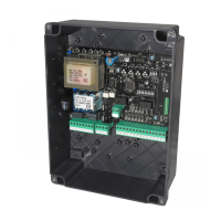
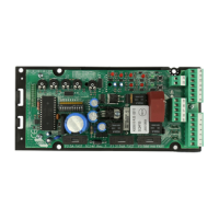
ELECTRICAL CONNECTIONS: FASTONS
ELECTRICAL CONNECTIONS: TERMINAL BOARDS
PROTECTION FUSES
Position Signal Description
1 0 Vac TRANSFORMER 0 VAC CONNECTION (BLACK CABLE)
2 18 Vac TRANSFORMER 18 VAC CONNECTION (ORANGE CABLE)
3 24 Vac TRANSFORMER 24 VAC CONNECTION (RED CABLE)
Terminal Position Signal Description
1 0 Vac 0 VAC output to the BATTERY CHARGER BOARD
2 + 24 Vac 24 VAC output to the BATTERY CHARGER BOARD
3 +SK BAT Positive connection to the BATTERY CHARGER BOARD
4 -SK BAT Negative connection to the BATTERY CHARGER BOARD
5 LAMP
Flashlight output 24V 10W max (slow flashing during opening, off with gate open, fast flashing during closing); it can
also be connected to the battery charger board
6
WARNING
LIGHT
Warning light output 24V 3W max (slow flashing during opening, on fixed with gate open, fast flashing during closing)
M1
7 COM COMMON INPUTS/OUTPUTS
8 OPT NOT USED
9 STOP STOP input (N.C.). If not used, jumper with terminal 14
10 START START input (N.O.)
11 PED PEDESTRIAN input (N.O.)
12 PHOTO PHOTOCELL input (N.C.). If not used, jumper with terminal 14
13 SAFETY SAFETY DEVICE input (N.C.). If not used, jumper with terminal 14 and set DIP 4 to OFF
M2
14 COM COMMON INPUTS/OUTPUTS
15 MOTOR OPEN 24V motor output - open
16
MOTOR CLOSE
24V motor output - close
17 + ACCES +24 VDC external accessory power supply (photocells, radio, etc.)
18 + SAFETY
24 VDC power supply for external safety devices (frame), active only during the operating cycle; connect the devices
on which to run the safety test to this input (also see DIP 4)
19 COM COMMON INPUTS/OUTPUTS
20 FCA Opening limit switch input
M3
21 FCC Closing limit switch input
N.B. Do not connect if the board is assembled on the operator
22 GND ANTENNA BRAID input
M5
23 ANT ANTENNA SIGNAL input
Position Value Type Description
F1 315 mA
FAST-
BLOW
Protects the ACCESSORY and SAFETY DEVICE power supply
F2 5A
FAST-
BLOW
Protects the control unit at the 24 VAC power supply input
F3 500 mA
FAST-
BLOW
Protects the flashlight output
11
 Loading...