Note, the wire colors are just suggestions. Obviously it will work with other colors as well. But for
the sake of not making mistakes, please at least use black and red for ground and +5V respectively.
Please refer to the drawing of the user port header, in order to see where to connect your wire leads.
USER PORT.
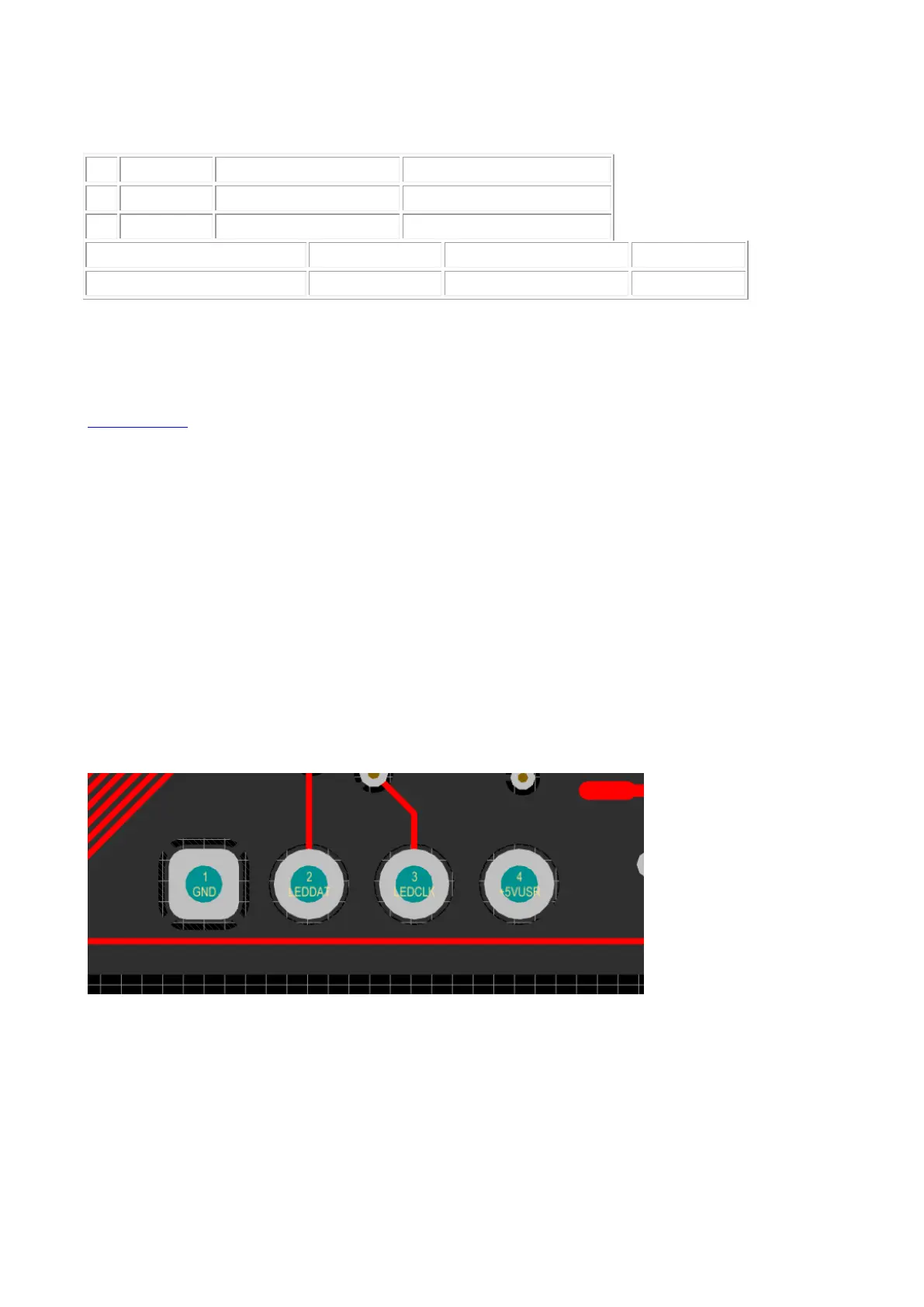
LED pinheader P8
Beginning with hardware revision 1.4 you’ll find the new LEDstrip pin header P8 to the left under
the User Port. This can be used to attach an APA102C LED strip and simultaneously use the User
Port for other purposes.
The pin header is defined as follows:
P8————–
Pin: 1 2 3 4
GND DAT CLK 5V
W A R N I N G ! Please always use extreme caution!
Please be extremly careful not to shorten the 5V to ground! It will burn a ferrite bead on your board!
Also shorting 5V to pin 3 or any other FPGA pin will likely damage the FPGA!
 Loading...