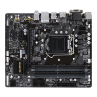
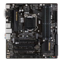
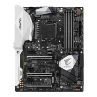
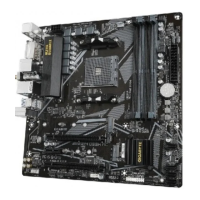
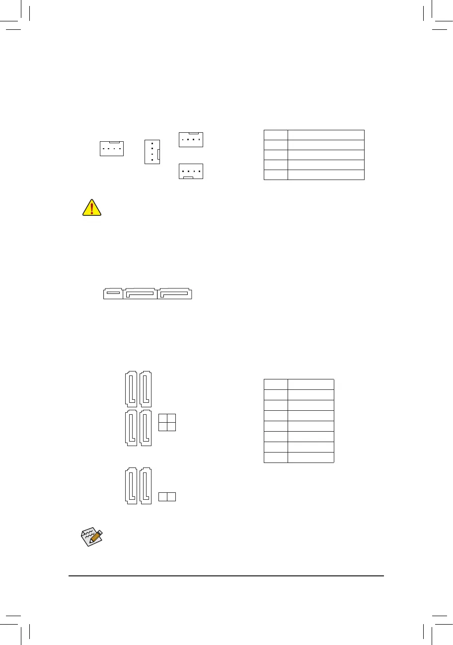
5) SATA EXPRESS (SATA Express Connector)
Each SATA Express connector supports a single SATA Express device. Note: The SATA Express connector
is not compatible with regular SATA devices.
6) SATA3 0/1/2/3/4/5 (SATA 6Gb/s Connectors)
The SATA connectors conform to SATA 6Gb/s standard and are compatible with SATA 3Gb/s and SATA 1.5Gb/s
standard. Each SATA connector supports a single SATA device.
Pin No. Denition
1 GND
2 TXP
3 TXN
4 GND
5 RXN
6 RXP
7 GND
To enable hot-plugging for the SATA ports, refer to Chapter 2, "BIOS Setup," "Peripherals\SATA And
RSTConguration,"formoreinformation.
F_USB30
F_U
B_
F_ F_
_
B
BS_
B
SB_
B
_S
S_
_
B
_U
_
B
S
123
123
123
123
1
1
1
1
BSS
S
_S
SSU
1 2 3
S3
BSSS
U
__ 3
F_USB3F
S _
S _
S _
SF
B_
B_
F
_0
S
S
_0F
_F
_
_
__B
U
S _S
_
USB0_B
B_
3/4) CPU_FAN/SYS_FAN1/SYS_FAN2/SYS_FAN3 (Fan Headers)
All fan headers on this motherboard are 4-pin. Most fan headers possess a foolproof insertion design.
When connecting a fan cable, be sure to connect it in the correct orientation (the black connector wire is
the ground wire). The speed control function requires the use of a fan with fan speed control design. For
optimum heat dissipation, it is recommended that a system fan be installed inside the chassis.
• Be sure to connect fan cables to the fan headers to prevent your CPU and system from overheating.
Overheating may result in damage to the CPU or the system may hang.
• Thesefanheadersarenotcongurationjumperblocks.Donotplaceajumpercapontheheaders.
SYS_FAN1
CPU_FAN
1
1
SYS_FAN3
1
SYS_FAN2
1
Pin No. Denition
1 GND
2 Voltage Speed Control
3 Sense
4 PWM Speed Control
SATA3
SATA3
1 0
3 2
5 4
1
1
1
1
7
7
7
7
- 14 -
 Loading...