The front panel design may differ by chassis. A front panel module mainly consists of power switch,
reset switch, power LED, hard drive activity LED, speaker and etc. When connecting your chassis
front panel module to this header, make sure the wire assignments and the pin assignments are
matched correctly.
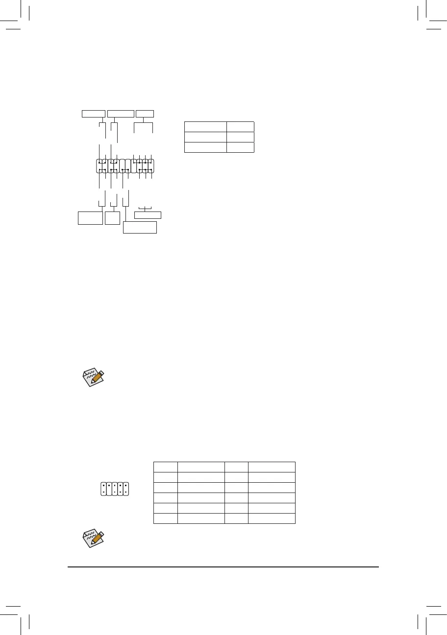
9) F_PANEL (Front Panel Header)
Connect the power switch, reset switch, speaker, chassis intrusion switch/sensor and system status indicator
on the chassis to this header according to the pin assignments below. Note the positive and negative pins
before connecting the cables.
System Status LED
S0 On
S3/S4/S5 Off
• PW (Power Switch):
Connects to the power switch on the chassis front panel. You may
congure the wayto turn offyour system using the power switch
(refer to Chapter 2, "BIOS Setup," "Settings\Platform Power," for more
information).
• PLED/PWR_LED (Power LED):
Connects to the power status indicator
on the chassis front panel. The LED is on
when the system is operating. The LED is
off when the system is in S3/S4 sleep state
or powered off (S5).
• SPEAK (Speaker):
Connects to the speaker on the chassis front panel. The system reports system startup status by issuing
a beep code. One single short beep will be heard if no problem is detected at system startup.
• HD (Hard Drive Activity LED):
Connects to the hard drive activity LED on the chassis front panel. The LED is on when the hard drive
is reading or writing data.
• RES (Reset Switch):
Connects to the reset switch on the chassis front panel. Press the reset switch to restart the computer
if the computer freezes and fails to perform a normal restart.
• CI (Chassis Intrusion Header):
Connects to the chassis intrusion switch/sensor on the chassis that can detect if the chassis cover has
been removed. This function requires a chassis with a chassis intrusion switch/sensor.
• NC: No connection.
10) F_AUDIO (Front Panel Audio Header)
ThefrontpanelaudioheadersupportsHighDenitionaudio(HD).Youmayconnectyourchassisfront
panel audio module to this header. Make sure the wire assignments of the module connector match the
pin assignments of the motherboard header. Incorrect connection between the module connector and the
motherboard header will make the device unable to work or even damage it.
Some chassis provide a front panel audio module that has separated connectors on each wire
instead of a single plug. For information about connecting the front panel audio module that has
different wire assignments, please contact the chassis manufacturer.
Pin No. Denition Pin No. Denition
1 MIC2_L 6 Sense
2 GND 7 FAUDIO_JD
3 MIC2_R 8 No Pin
4 NC 9 LINE2_L
5 LINE2_R 10 Sense
1
2
9
10
Power LED
Power LED
Hard Drive
Activity LED
Reset
Switch
Chassis Intrusion
Header
Power Switch
Speaker
SPEAK+
SPEAK-
NC
NC
1
2
19
20
CI-
CI+
PLED-
PW-
PLED+
PW+
HD-
RES+
HD+
RES-
F_USB30
F_AUDIO(H)
DB_PORT
F_PANEL(NH) F_PANEL
(H61M-D2)
ACPI_CPT
(GA-IVB)
BIOS_PH
(GA-IVB)
SMB_CPT
(GA-IVB)
CLR_CMOS
CI
DIS_ME
GP15_CPT
(GA-IVB)
XDP_CPU
XDP_PCH
(GA-IVB)
TPM
w/housing
Voltage measurement module(X58A-OC)
PCIe power connector (SATA)(X58A-OC)
DIP
123
DIP
123
DIP
123
DIP
123
1
1
1
1
BIOS Switcher (X58A-OC)
PWM Switch (X58A-OC)
M_SATA
PWM Switch (SW1)(X79-UD7)
DIP
1 2 3 4 5
Voltage measurement points(G1.Sniper 3)
BIOS Switcher (SW4)
GAIN
PCIe Control (Z87X-UP7)
ATX_12V_2X3
F_USB3 (Front Panel)
SATA_Express
SATA_Express
SATA_Express
PCIe/DIMM Control (Z97X-SOC Force)
M.2
MINI PCIE
THB_C
THB_C
M.2 Wi-Fi
M2_10G
Subzero
Sense
M2_10G with WIFI module
M2_WIFI
LED_IO (4-pin)
J_HDMI(NH)
OC_LED/OC_BT
M.2
MINI PCIE
U.2
SATA_SGP
LED_C(5-pin)
SPDIF_O (4-pin)
BAT
USB20_OB
THB_C
THB_C1
F_USB31C
eDP
F_USB30/31C
VROC
TPM_new
GPIOX8
M2_32G with GC-M2-U2
SPI_TPM
PW_SW
SYS_FAN
EXT_PWR
LED_DDR
PWR_LED-
PWR_LED+
PWR_LED-
- 16 -
 Loading...