- 24 -Hardware Installation
1-9 Onboard Buttons, Switches, and LEDs
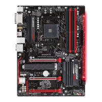
BIOS Switch and BIOS LED Indicators
The BIOS switch (SW4) allows users to easily select a different BIOS for boot up or overclocking, helping to reduce
BIOS failure during overclocking. The LED indicator (MBIOS_LED/BBIOS_LED) shows which BIOS is active.
BBIOS_LED (The backup BIOS is active)
MBIOS_LED (The main BIOS is active)
BIOS LED Indicators:
3: Backup BIOS (Boot from the backup BIOS)
1: Main BIOS (Boot from the main BIOS)
BIOS Switch:
SW4
Quick Buttons
This motherboard has 3 quick buttons: power button, reset button and clear CMOS button. The power button
and reset button allow users to quickly turn on/off or reset the computer in an open-case environment when they
want to change hardware components or conduct hardware testing. Use this button to clear the CMOS values
(e.g. date information and BIOS congurations) and reset the CMOS values to factory defaults when needed.
PW_SW: Power button
RST_SW: Reset button
CMOS_SW: Clear CMOS button
• Always turn off your computer and unplug the power cord from the power outlet before clearing
the CMOS values.
• After system restart, go to BIOS Setup to load factory defaults (select Load Optimized
Defaults) or manually congure the BIOS settings (refer to Chapter 2, "BIOS Setup," for BIOS
congurations).
F_USB30
F_AUDIO(H)
DB_PORT
F_PANEL(NH) F_PANEL
(H61M-D2)
ACPI_CPT
(GA-IVB)
BIOS_PH
(GA-IVB)
SMB_CPT
(GA-IVB)
CLR_CMOS
CI
DIS_ME
GP15_CPT
(GA-IVB)
XDP_CPU
XDP_PCH
(GA-IVB)
TPM
w/housing
Voltage measurement module(X58A-OC)
PCIe power connector (SATA)(X58A-OC)
DIP
1 2 3
DIP
1 2 3
DIP
1 2 3
DIP
123
1
1
1
1
BIOS Switcher (X58A-OC)
PWM Switch (X58A-OC)
M_SATA
PWM Switch (SW1)(X79-UD7)
DIP
1 2 3 4 5
Voltage measurement points(G1.Sniper 3)
BIOS Switcher (SW4)

 Loading...