- 16 -
System Appearance
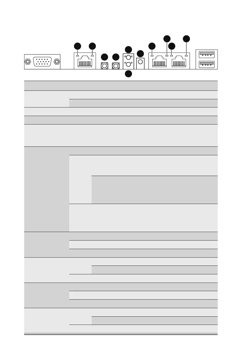
2-4 Rear System Button and LEDs
No. Name Color Status Description
1.
Power Button
with LED
Green On System is powered on
N/A Off System is not powered on or in ACPI S5 state (power off)
2.
ID Button Press the button to activate system identication
3.
Reset Button Press the button to reset the system.
4.
NMI button
Press the button server generates a NMI to the processor
if the multiple-bit ECC errors occur, which effectively halt
the server.
5.
System
Status LED
Green Solid On System is operating normally.
Amber
Solid On
Critical condition, may indicate:
System fan failure
System temperature
Blink
Non-critical condition, may indicate:
Redundant power module failure
Temperature and voltage issue
Chassis intrusion
N/A Off
System is not ready, may indicate:
POST error
NMI error
Processor or terminator missing
6.
10GbE
Speed LED
Green On 10 Gbps data rate
Yellow On 5Gbps, 2.5Gbps, 1Gbps data rate
N/A Off 100 Mbps data rate
7.
10GbE Link /
Activity LED
Green
On Link between system and network or no access
Blink Data transmission or reception is occurring.
N/A Off No data transmission or reception is occurring.
8.
1GbE Speed
LED
Yellow On 1 Gbps data rate
Green On 100 Mbps data rate
N/A Off 10 Mbps data rate
9.
1GbE Link /
Activity LED
Green
On Link between system and network or no access
Blink Data transmission or reception is occurring.
N/A Off No data transmission or reception is occurring.
1 2
3
5
6
6
8 9
 Loading...