- 25 - Hardware Installation
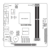
11) F_USB1/F_USB2 (USB 2.0/1.1 Headers)
TheheadersconformtoUSB2.0/1.1specication.EachUSBheadercanprovidetwoUSBportsviaan
optional USB bracket. For purchasing the optional USB bracket, please contact the local dealer.
Do not plug the IEEE 1394 bracket (2x5-pin) cable into the USB 2.0/1.1 header. •
Prior to installing the USB bracket, be sure to turn off your computer and unplug the power •
cord from the power outlet to prevent damage to the USB bracket.
When the system is in S4/S5 mode, only the USB ports routed to the F_USB1 header can sup-
port the ON/OFF Charge function.
Pin No. Denition
1 Power (5V)
2 Power (5V)
3 USB DX-
4 USB DY-
5 USB DX+
6 USB DY+
7 GND
8 GND
9 No Pin
10 NC
2
10
1
9
12) CI (Chassis Intrusion Header)
This motherboard provides a chassis detection feature that detects if the chassis cover has been re-
moved. This function requires a chassis with chassis intrusion detection design.
1
Pin No. Denition
1 Signal
2 GND
 Loading...