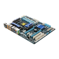
- 23 - Hardware Installation
6) SATA2 1/2/3/4 (SATA 3Gb/s Connectors, Controlled by Intel B75 Chipset)
The SATA connectors conform to SATA 3Gb/s standard and are compatible with SATA 1.5Gb/s standard.
Each SATA connector supports a single SATA device.
Pin No. Definition
1 GND
2 TXP
3 TXN
4 GND
5 RXN
6 RXP
7 GND
SATA2
7
7
1
1
1
2
3
4
Please connect the L-shaped end of
the SATA cable to your SATA hard
drive.
7) mSATA (Solid-State Drive Connector, Controlled by the Intel B75 Chipset)
The mSATA connector conforms to SATA 3Gb/s standard and can connect to a single solid-state
drive.
F_USB30
F_AUDIO(H)
DB_PORT
F_PANEL(NH) F_PANEL
(H61M-D2)
ACPI_CPT
(GA-IVB)
BIOS_PH
(GA-IVB)
SMB_CPT
(GA-IVB)
CLR_CMOS
CI
DIS_ME
GP15_CPT
(GA-IVB)
XDP_CPU
XDP_PCH
(GA-IVB)
TPM
w/housing
Voltage measurement module(X58A-OC)
PCIe power connector (SATA)(X58A-OC)
DIP
1 2 3
DIP
1 2 3
DIP
1 2 3
DIP
123
1
1
1
1
BIOS Switcher (X58A-OC)
PWM Switch (X58A-OC)
M_SATA
PWM Switch (SW1)(X79-UD7)
DIP
1 2 3 4 5
 Loading...
