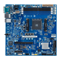
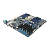
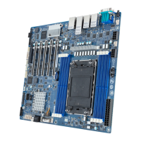
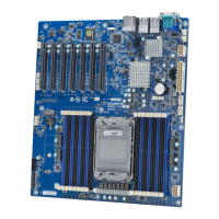
No. Code Descripon
1 AUDIO Audio connectors
2 USB31_LAN2 GbE LAN port #2 (top) / USB 3.0 ports (boom)
3 USB31_LAN1 GbE LAN port #1 (top) / USB 3.0 ports (boom)
4 VGA_DVI VGA port (top)/DVI-D port (boom)
5 HDMI HDMI 1.4 port
6 COM1 Serial port
7 SYS_FAN1 System fan connector #1
8 ATX_12V 8 pin power connector (for CPU)
9 CPU_FAN CPU fan connector
10 ATX 24 pin main power connector
11 SYS_FAN2 System fan connector#2
12 SATA0 SATA 3 6Gb/s connector #0
13 SATA1 SATA 3 6Gb/s connector #1
14 SATA3 SATA 3 6Gb/s connector #3
15 SATA2 SATA 3 6Gb/s connector #2
16 F_PANEL Front panel header
17 FUSB2_2 USB 2.0 connector #2
18 FUSB2_1 USB 2.0 connector #1
19 BAT Baery socket
20 CLR_CMOS Clear CMOS jumper
21 COM4 Serial port cable connector #4
22 COM3 Serial port cable connector #3
23 COM2 Serial port cable connector #2
24 FP_AUDIO Front audio connector
25 PCIEX1_2 PCI Express x1 slot (PCIe x1 Signal)
26 PCIEX4 PCI Express x4 slot (PCIe x2 Signal)
27 PCIEX1_1 PCI Express x1 slot (PCIe x1 Signal)
28 PCIEX6 PCI Express x16 slot (PCIe x16 Signal)
DDR4_1
DDR4_3
CPU
1 2 3 4
5 6
7
8
9
101112131415
16
17
18
19
20
21
22
23
24
25 26 27 28
Clear CMOS
CLR_CMOS
Default
Enable
Front Panel Header/ 前面板
No. Pin Define
1 HDD LED+
2 Power LED+
3 HDD LED-
4 Power LED-
5 GND
6 Power Buon+
7 Reset Buon
8 Power Buon-
9 No Connect
10 No Pin
1
109
2
ATX Power/ 电源
1
13
12
24
No. Pin Define
1 GND
2 GND
3 GND
4 GND
5 +12V
6 +12V
7 +12V
8 +12V
No. Pin Define
1 3.3V
2 3.3V
3 GND
4 +5V
5 GND
6 +5V
7 GND
8 Power Good
9 5VSB
10 +12V
11 +12V
12 3.3V
No. Pin Define
13 3.3V
14 -12V
15 GND
16 PS_ON
17 GND
18 GND
19 GND
20 -5V
21 +5V
22 +5V
23 +5V
24 GND
15
48
Installing CPU/ 安装 CPU
Memory Populaon Configuraon/ 安装内存
Memory
Type
Voltage (V)
Speed (MT/s)
Channels
DIMM Per Channel
2666 2400
DDR4
1.2V
1,2
1,2
DIMM Capacity (GB) 2,4,6,8
UDIMM
Connector
1
2
2
All channels in system run at the fastest common frequency.
UDIMM 2666 two DIMMs per channel (2DPC) is supported when channel is populated with the same UDIMM
memory module.
所有通道模式以最快速率速度运行。
UDIMM 2666支持每通道两个DIMM(2DPC)當每通道安裝相同速率速度的UDIMM内存模块。
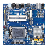
Rear I/O Connector/ 后面板接口
Off
State Description
Yellow On 1Gbps data rate
Green On 100Mbps data rate
10Mbps data rate
5 6
No. Desripon
1 Serial Port
2 HDMI 1.4 Port
3 VGA Port
4 DVI-D Port
5 GbE Eternet LAN Port #1
6 GbE Eternet LAN Port #2
The HDMI connector is HDCP compliant and supports Dolby True HD and DTS HD
Master Audio formats. It also supports up to 192KHz/24bit 8-channel LPCM audio
output. You can use this port to connect your HDMI-supported monitor. The
maximum supported resoluon is 4096x2160@24Hz or 2560x1600@60Hz, but the
actual resoluons supported are dependent on the monitor being used.
10/100/1000 LAN LED:
Speed LED Link/Acvity
LED
1
2
3
4
5 6
7 7
8
9
10
No. Descripon
7 USB 3.0 Port
8 Line In
9 Line Out
10 Mic In
SATA Connector/SATA 接口
1
7
1
7
7
1
7
1
No. Pin Define
1 GND
2 TXP
3 TXN
4 GND
5 RXN
6 RXP
7 GND
COM2 Connector
21
109
No. Pin Define
1 NDCD-
2 NSIN
3 NSOUT
4 NDTR-
5 GND
6 NDSR-
7 NRTS-
8 NCTS-
9 NRI-
10 No Pin
CPU/System FAN/ 风扇
1
4
14
No. Pin Define
1 GND
2 +12V
3 Sense
4 Speed Control
USB 2.0 Header
No. Pin Define
1 Power (5V)
2 Power (5V)
3 USB DX-
4 USB DY-
5 USB DX+
21
109
No. Pin Define
6 USB DY+
7 GND
8 GND
9 No Pin
10 No Connect
Front Audio Connector/ 前置音频
No. Pin Define
1 MIC2_L
2 GND
3 MIC2_R
4 FP_AUDIO_DET
5 LINE2_R
6 GND
7 F_Audio_JD
8 No Pin
9 LINE2_L
10 GND
21
109
Jumper Sengs/ 跳线设置
System Baery
1
2
MCH31AM Quick Reference Guide/
快速测试参考指南
PN.12ME0-MCH310-00H