1 2
3 4 5
6
7
8
9
11
10
12
13
14
15
68
69
67
66
65
64
19
18
20
21
22
23
29
28
30
31
32
33
16
17
26
24
252734353637
40
47
48
49
50
51
52
53
54
55
56
63
62
44
43
42
41
39
38
61
60
45
59
58
57
46
Front Panel Header/ 前面板 HDD Back Plane Board Header/ 硬盤背板排針
ATX Power/ 电源
PMBUS
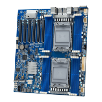
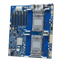
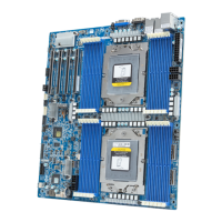
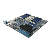
Installing CPU/ 安装处理器 Memory Populaon Configuraon/ 安装内存
Type
Ranks Per
DIMM and
Data Width
Speed (MT/s);
Slot Per Channel (SPC) and DIMM Per Channel (DPC)
RDIMM
RDIMM
RDIMM
RDIMM
LRDIMM
SRx4
2133
2133
2133
2133
2133
2133
2133
2133
2133
2133
1866
1866
1866
1866
2133
1 Slot Per Channel
1DPC
2 Slot Per Channel
1DPC 2DPC
SRx8
DRx8
DRx4
QRx4
Rear I/O Connector/ 后面板接口
Off
State Description
Yellow On 1Gbps data arte
Green On 100Mbps data arte
10Mbps data arte
SATA Connector/SATA 接口
1
7
SATA/sSATA SGPIO Header/ 串行 GPIO
1 7
2 8
No. Pin Define
1 Data In
2 No Pin
3 Data Out
4 GND
5 GND
6 Load
7 No Connect
8 Clock
TPM Connector/ 可信平台模块
BMC Firmware Readiness LED
State Descripon
On BMC firmware is inial
Blink BMC firmware is ready
Off AC loss
BMC Firmware Readiness LED (LED_BMC):
Intel Raid Header
1
2
No. Pin Define
1 Key Pin
2 GND
Intel RAID Key Header (SW_RAID):
CPU/System FAN/ 风扇
USB 3.0 Header
IPMB
Case Open Intrusion Header
Jumper Sengs/ 跳线设置
1
2
3
4
5
6
7
1 2 3 3
6
6
4
4
5
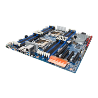
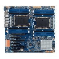
MD80-TM1 Quick Reference Guide/ 快速测试参考指南
1
1
1
1
4
4
1
3
5
15
48
1
2423
2
1 2
13 14
1 2
120
1011
25 26
No. Pin Define
1 3.3V
2 3.3V
3 GND
4 +5V
5 GND
6 +5V
7 GND
8 Power Good
9 5VSB
10 +12V
11 +12V
12 3.3V
No. Pin Define
1 GND
2 GND
3 GND
4 GND
No. Pin Define
1 PMBus Clock
2 PMBus Data
3 PMBus Alert
4 GND
5 3.3V Sense
No. Pin Define
1 Clock
2 GND
3 Data
No. Pin Define
1 GND
2 +12V
3 Sensor
4 Speed Control
No. Pin Define
1 GND
2 TXP
3 TXN
4 GND
5 RXN
6 RXP
7 GND
No. Pin Define
1 CLK_33M_TPM_CONN
2 P_3V3_AUX
3 LPC_RST
4 P3V3
5 LPC_LAD0
6 IRQ_SERIAL
7 LPC_LAD1
8 No Connect
9 LPC_LAD2
10 NC
11 LPC_LAD3
12 GND
13 LPC_FRAME_N
14 GND
Open: Normal operaon.
Closed: Acve chassis intruson alert.
No. Pin Define
1 Power
2 IntA_P1_SSRX-
3 IntA_P1_SSRX+
4 GND
5 IntA_P1_SSTX-
6 IntA_P1_SSTX+
7 GND
8 IntA_P1_D-
9 IntA_P1_D+
10 No Connect
11 IntA_P2_D+
12 IntA_P2_D-
13 GND
14 IntA_P2_SSTX+
15 IntA_P2_SSTX-
16 GND
17 IntA_P2_SSRX+
18 IntA_P2_SSRX-
19 Power
20 No Pin
No. Code Descripon
1 CPU1_FAN CPU1 fan connector (for Secondary CPU)
2 SW_ID ID switch buon
3 USB3_MLAN BMC Management LAN port (top) / USB 3.0 ports (boom)
4 LAN1 LAN port #1
5 LAN2 LAN port #2
6 VGA VGA port
7 COM1 Serial port
8 P12V_AUX2 8 pin power connector (for secondary CPU)
9 PMBUS PMBus connector
10 DIMM_P1_G0 Channel 3 slot 0 (for secondary CPU)
11 DIMM_P1_G1 Channel 3 slot 1 (for secondary CPU)
12 DIMM_P1_G2 Channel 3 slot 2 (for secondary CPU)
13 DIMM_P1_H0 Channel 4 slot 0 (for secondary CPU)
14 DIMM_P1_H1 Channel 4 slot 1 (for secondary CPU)
15 DIMM_P1_H2 Channel 4 slot 2 (for secondary CPU)
16 CPU1 Intel LGA2011 Socket R (Secondary CPU)
17 ATX1 24 pin main power connector
18 DIMM_P0_A0 Channel 1 slot 0 (for primary CPU)
19 DIMM_P0_A1 Channel 1 slot 1 (for primary CPU)
20 DIMM_P0_A2 Channel 1 slot 2 (for primary CPU)
21 DIMM_P0_B0 Channel 2 slot 0 (for primary CPU)
22 DIMM_P0_B1 Channel 2 slot 1 (for primary CPU)
23 DIMM_P0_B2 Channel 2 slot 2 (for primary CPU)
24 P12V_AUX1 8 pin power connector (for primary CPU)
25 SYS_FAN5 System fan connector#5
26 CPU0 Intel LGA2011 Socket R (Primary CPU)
27 CPU0_FAN CPU0 fan connector (for Primary CPU)
28 DIMM_P0_D2 Channel 4 slot 2 (for primary CPU)
29 DIMM_P0_D1 Channel 4 slot 1 (for primary CPU)
30 DIMM_P0_D0 Channel 4 slot 0 (for primary CPU)
31 DIMM_P0_C2 Channel 3 slot 2 (for primary CPU)
32 DIMM_P0_C1 Channel 3 slot 1 (for primary CPU)
33 DIMM_P0_C0 Channel 3 slot 0 (for primary CPU)
34 SYS_FAN4 System fan connector#4
35 SYS_FAN3 System fan connector#3
No. Pin Define
1 Power LED+
3 No Pin
5 Power LED-
7 HDD LED+
9 HDD LED-
11 Power Buon
13 GND
15 Reset Buon+
17 GND
19 ID Switch+
21 ID Switch-
23 NMI Switch-
No. Desripon
1 Serial port
2 Video port
3 GbE Eternet LAN ports
4 KVM Server Management 10/100/1000 LAN Port (Dedicated LAN Port)
5 USB 3.0 ports
6 Power buon/LED
No. Desripon
1 Clear CMOS Jumper
1-2 Close: Normal operaon (Default seng)
2-3 Close: Clear CMOS data.
2 Force to Stop FRB Timer Jumper
1-2 Close: Normal operaon. (Default seng)
2-3 Close: Force to Stop FRB Timer.
3 S3 Power On Select Jumper
1-2 Close: Stop an inial power on when BMC is not ready.
2-3 Close: Keep inial power on. (Default seng)
4 BIOS Recovery Jumper
1-2 Close: Normal operaon. (Default seng)
2-3 Close: BIOS recovery mode.
5 Clearing Supervisor Password Jumper
1-2 Close: Normal operaon. (Default seng)
2-3 Close: Skip supervisor password.
When only one DIMM is used, it must be populated in memory slot0 first.
Memory populated sequence must be followed with slot0/slot1/slot2
System will not boot normally with incorrect populated sequence.
Speed LED
Power buon/LED:
10/100/1000 LAN LED:
Link/Acvity
LED
13
12
24
No. Code Descripon
36 SYS_FAN2 System fan connector#2
37 SYS_FAN1 System fan connector#1
38 SSATA_SGP sSATA SGPIO header
39 SATA_SGP SATA SGPIO header
40 SATA0/1/2/3/4/5 SATA 3 6Gb/s connectors
41 SW_RAID Intel Soware RAID Key jumper
42 CASE_OPEN Case open intrusion alert header
43 ME_UPDATE ME update jumper
44 ME_RCVR ME recovry jumper
45 BIOS_PWD Clearing Supervisor Password jumper
46 BIOS_RCVR BIOS recovery jumper
47 SSATA0/1/2/3 SATA 3 6Gb/s connectors
48 F_USB3 USB 3.0 header
49 FP_1 Front panel header
50 IPMB IPMB connector
51 BP_1 HDD back plane board header
52 TPM TPM module connector
53 PCIE_1 PCI Express x8 slot
54 PCIE_2 PCI Express x8 slot
55 PCIE_3 PCI Express x8 slot
56 PCIE_4 PCI Express x16 slot
57 LED_BMC BMC firmware readiness LED
58 BMC_FRB Force to Stop FRB Timer jumper
59 S3_MASK S3 Power On Select jumper
60 BUZZER1 Buzzer
61 CLR_CMOS Clear CMOS jumper
62 M2_SK M.2 slot
63 BAT Baery socket
64 DIMM_P1_E0 Channel 4 slot 0 (for secondary CPU)
65 DIMM_P1_E1 Channel 4 slot 1 (for secondary CPU)
66 DIMM_P1_E2 Channel 4 slot 2 (for secondary CPU)
67 DIMM_P1_F0 Channel 3 slot 0 (for secondary CPU)
68 DIMM_P1_F1 Channel 3 slot 1 (for secondary CPU)
69 DIMM_P1_F2 Channel 3 slot 2 (for secondary CPU)
Green On
Off
Description
System is powered on
System is powered off
State
No. Pin Define
13 3.3V
14 -12V
15 GND
16 PS_ON
17 GND
18 GND
19 GND
20 -5V
21 +5V
22 +5V
23 +5V
24 GND
No. Pin Define
5 +12V
6 +12V
7 +12V
8 +12V
No. Pin Define
2 5V Standby
4 ID LED+
6 ID LED-
8 System Status LED (Green)
10 System Status LED (Amber)
12 LAN1 Acve LED+
14 LAN1 Link LED-
16 SMBus Data
18 SMBus Clock
20 Case Open
22 LAN2 Acve LED
24 LAN2 Link LED-
No. Pin Define
1 BP_SGP_CLK
3 BP_SGP_GLD
5 BP_SGP_DOUT
7 Key Pin
9 GND
11 BP_LED_G_N
13 BP_SGP_DIN
15 GND
17 GND
19 P_3V3_AUX
21 P_3V3_AUX
23 GND
25 BP_PRESENSE
No. Pin Define
2 No Connect
4 FAN_SGP_GLD
6 GND
8 Reset
10 BP_LED_A_N
12 GND
14 No Connect
16 SMB_BP_DATA
18 SMB_BP_CLK
20 BMC_ACK
22 BMC_REQ
24 Key Pin
26 GND
只使用一个DIMM时,必须安装到内存插槽0。
内存安装顺序必须是 插槽0/插槽1/插槽2。
若安装顺序有误,系统将无法正常 开机。
No. Desripon
6 ME Recovery Jumper
1-2 Close: Normal operaon. (Default seng)
2-3 Close: ME recovery mode.
7 ME Update Jumper
1-2 Close: Normal operaon (Default seng)
2-3 Close: ME update.
P/N:12QM1-MD80T0-00R