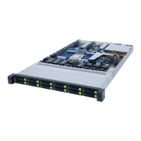
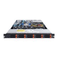
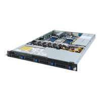
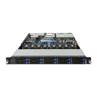
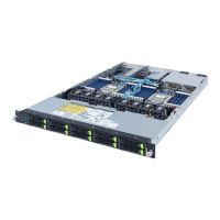
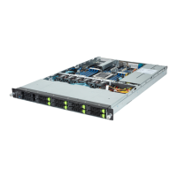
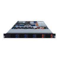
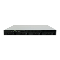
- 19 - System Appearance
2-3 Front Panel LEDs and Buttons
L2 SYS
ID
L1
RST
NMI
1 2 3 4 5 6 7 8
No. Name Color Status Description
1.
NMI Button -- --
Press this button for the server to generate a NMI to the
processor. If multiple-bit ECC errors occur, the server
will effectively be halted.
2.
Reset button -- -- Press this button to reset the system.
3./4.
LAN 1/2
Active/Link
LEDs
Green On
Indicates a link between the system and the network
or no access.
Green Blink
Indicates data trasmission or receiving is occuring.
N/A Off
Indicates no data transmission
or receiving is occuring.
5.
HDD Status
LED
Green
On
Indicates locating the HDD.
Blink
Indicates accessing the HDD.
Amber On
Indicates HDD error.
Green/
Amber
Blink
Indicates HDD rebuilding.
N/A Off
Indicates no HDD access or no HDD error.
6.
System
Status LED
This LED represents the RoT function
LED behavior. Please see the following
section for detail LED behavior.
7.
ID Button
with LED
This LED represents the RoT function
LED behavior. Please see the following
section for detail LED behavior.
8.
Power button
with LED
Green On Indicates the system is powered on.
Green Blink System is in ACPI S1 state (sleep mode).
N/A Off
• System is not powered on or in ACPI S5 state
(power off)
• System is in ACPI S4 state (hibernate mode)

 Loading...