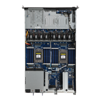
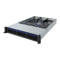
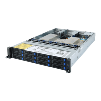
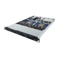
System Appearance - 18 -
2-3 Front Panel LED and Buttons
L2 SYS
ID
L1
RST
NMI
1
2 3 4 5 6
7 8
No. Name Color Status Description
1.
NMIbutton
PressthebuttonservergeneratesaNMItotheprocessor
ifthemultiple-bitECCerrorsoccur,whicheffectivelyhalt
theserver.
2.
Reset Button Pressthebuttontoresetthesystem.
3/4.
LAN1/2
Active/Link
LEDs
Green
Solid
On
Linkbetweensystemandnetworkornoaccess.
Green Blink Data trasmission or receiving is occuring
N/A Off Nodatatransmissionorreceivingisoccuring
5.
HDD Status
LED
Green
On HDD locate
Blink HDD access
Amber On HDD fault
Green/
Amber
Blink HDD rebuilding
N/A Off NoHDDaccessornoHDDfault.
6.
System
Status LED
Green
Solid
On
Systemisoperatingnormally.
Amber
Solid
On
Criticalcondition,mayindicate:
Systemfanfailure
Systemtemperature
Blink
Non-criticalcondition,mayindicate:
Redundantpowermodulefailure
Temperature and voltage issue
Chassisintrusion
N/A Off
Systemisnotready,mayindicate:
POST error
NMIerror
Processor or terminator missing
7.
IDButton Pressthebuttontoactivatesystemidentication
8.
Powerbutton
withLED
Green On Systemispoweredon
Green Blink SystemisinACPIS1state(sleepmode)
N/A Off
• Systemis notpowered onor inACPI S5 state
(poweroff)
• SystemisinACPIS4state(hibernatemode)
 Loading...