Do you have a question about the GILBARCO VEEDER-ROOT Encore 700 S and is the answer not in the manual?
Manual provides start-up and service information for the Encore 700 S CRIND system.
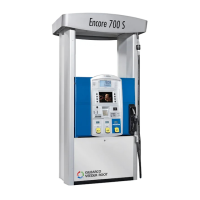
Details the Encore 700 S CRIND system, its compliance, and available options.
Explains warning symbols and signal words used in the manual to denote hazards.
Covers hazards and precautions related to fuels, vapors, and electrical energy.
Steps for configuring the CRIND device, including diagnostic card use.
Procedure for programming the CRIND ID for each side of the device.
Instructions for setting the CRIND operating mode (MOC or Generic).
Steps to configure network settings for older DCM2 versions.
Steps to configure network settings for newer DCM2.1 versions.
Procedure to reset all IP addresses to factory default values.
Detailed steps for setting IP addresses for CRIND, Server, Netmask, and Gateway.
Procedure to set the IP address for CRIND Side A.
Procedure to set the IP address for CRIND Side B.
Procedure to set the IP address for the SMART Merchandising Server.
Procedure to set the network mask address.
Procedure to set the gateway address.
How to activate the configured network settings.
Option to view the currently applied network configuration.
Procedure to hide network settings from view.
Steps to adjust the audio volume on the unit.
How to set the default personality screen for the customer display.
Procedure for setting the date and time on the CRIND device.
Visual diagrams illustrating the system's internal component connections.
Steps for performing post-installation diagnostics and visual inspections.
Details of the Printed Circuit Boards (PCBs) used in the Encore 700 S.
Details on the status and error LEDs on various boards.
Lists the physical connections and cable types for various boards.
Describes the status and function of the service LED.
Describes the status and function of the status/error LEDs.
Information on the FlexPay Control Board, its functions, and connections.
Details on the DCM2.2 module, its highlights, LEDs, connectors, and jumpers.
Explains the function of each LED indicator on the DCM2.2 module.
Details the status and meaning of DCM2.2 LED indicators.
Lists the DCM2.2 connectors and their respective functions.
Describes the status and functions of the jumpers on the DCM2.2 board.
General information about the activation process for FlexPay units.
Step-by-step guide to activating the Encore 700 S CRIND device.
Accessing and navigating the service menu for activation.
Menu for activating security mounting sensors and obtaining passwords.
The final screen confirming successful unit activation.
Indicates system package installation progress.
Indicates system error or alarm status.
Indicates system is activated and waiting for master connection.
Indicates system is running but not activated.
Table of common CRIND communication issues, their causes, and remedies.
Checklist items for the diagnostics mode setup.
Checklist items for visual inspection and transaction testing.
Steps to enable the "Enable Wireless Sync Option" for TRIND operation.
| Model | Encore 700 S |
|---|---|
| Type | Fuel Dispenser |
| Product Type | Fuel Dispenser |
| Manufacturer | GILBARCO VEEDER-ROOT |
| Payment Options | Cash, Credit/Debit Card, Fleet Cards |
| Display | LCD |
| Card Reader | EMV, NFC |
| Fuel Types Supported | Gasoline, Diesel |
| Operating Temperature | -40°C to +50°C |
| Storage Temperature | -40°C to 70°C |
| Communication Interface | RS-485, Ethernet |
| Power Supply | 120/240 VAC, 50/60 Hz |
| Certifications | UL, ATEX, IECEx |