EasyManua.ls Logo

GILBARCO VEEDER-ROOT Latitude LS-100 User Manual

GILBARCO VEEDER-ROOT Latitude LS-100
122 pages
To Next Page IconTo Next Page
Page #1 background imageLoading...
Page #1 background image
LATITUDE
Owner’s Manual
MDE-5422B

Table of Contents

Other manuals for GILBARCO VEEDER-ROOT Latitude LS-100

Question and Answer IconNeed help?

Do you have a question about the GILBARCO VEEDER-ROOT Latitude LS-100 and is the answer not in the manual?

GILBARCO VEEDER-ROOT Latitude LS-100 Specifications

General IconGeneral
ModelLatitude LS-100
CategoryPetrol Station Equipment
Power Supply100-240 VAC, 50/60 Hz
Enclosure RatingIP54
DisplayTouchscreen
ConnectivityEthernet, Wi-Fi

Summary

LATITUDE Owner's Manual

MDE-5422B Document Identifier

Document identifier for the manual.

Approvals

Underwriters Laboratories (UL) Approvals

Lists products certified by UL.

California Air Resources Board (CARB) Approvals

Lists products approved by CARB.

Trademarks

Non-registered Trademarks

List of trademarks not officially registered.

1 - Introduction

Purpose of the Manual

Explains the manual's objective and scope.

Intended Users

Identifies the target audience for this manual.

2 - Important Safety Information

Preliminary Precautions

Essential safety steps before operating or servicing.

6 - Preliminary Steps for Service

Preparing for Service

Steps to take before initiating a service call.

7 - Latitude Pump/Dispenser Maintenance

General Safety Considerations

General safety guidelines for equipment maintenance.

Inspecting Pump/Dispenser Periodically

Guidelines for regular equipment inspections.

8 - Troubleshooting

1 - Introduction

Support Information

Contact details for technical assistance and support.

Scope of Manual

Defines the information covered in the manual.

Related Documents

Document Number and Title

List of related technical documents with their numbers.

Abbreviations and Acronyms

Glossary of Terms

Glossary of technical terms and their definitions.

2 - Important Safety Information

Emergency Total Electrical Shut-Off

Procedure for emergency power cutoff.

Safety Symbols and Warning Words

Explains safety alert symbols and signal words used.

Working With Fuels and Electrical Energy

Hazards and precautions when working with fuels and electricity.

Working With Electricity Safely

Hazardous Materials

Information on handling materials inside electronic enclosures.

In an Emergency

Inform Emergency Personnel

Steps to provide information to emergency responders.

Hazards and Actions

WARNING: Fuel Hazards

Critical safety warning regarding fuel hazards.

3 - Supplementary Instructions for European Union (EU) Countries

Sample Declaration of Conformity

Document confirming compliance with EU directives.

Markings Related to Explosive Atmospheres (ATEX) Directive

Specifications

Technical parameters of the dispenser.

Zoning Diagram

Zone 0 Definition

Area with continuous presence of explosive atmosphere.

Zone 1 Definition

Area where explosive atmosphere may occur occasionally.

Zone 2 Definition

Area where explosive atmosphere is unlikely to occur.

Zoning Diagram

Island High Hose Zoning

Zoning for island configuration with high hose placement.

Island Low Hose Zoning

Zoning for island configuration with low hose placement.

Zoning Diagram

Hazardous Area for 4 Grade Models Without Hose Retraction

Hazardous area zoning for specific 4-grade models.

Hazardous Area for 4 Grade Models With Hose Retraction

Hazardous area zoning for models with hose retraction.

Material Compatibility

Important Information on Compatibility

Crucial notes on material compatibility for dispenser use.

4 - Latitude Components

Dispenser Overview

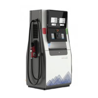
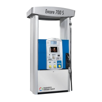
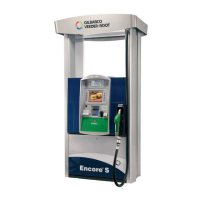
Overview of the Latitude dispenser and its main parts.

Front View Components

Diagram showing the front components of the dispenser.

Side View Components

Diagram showing the side components of the dispenser.

Common Functions

Keypad Description

Description of the dispenser's keypad layout and functionality.

Using the Keypad

Functions that can be performed using the keypad.

Keypad LCD Display

Details about the dispenser's Liquid Crystal Display.

PIN of each Level Command

Premium Features

Premium Canopy Features

Details about the premium canopy features.

Premium Features

Skylight LED Strips

Information on skylight LED strips for image enhancement.

Vapor Recovery and Monitoring System

Explanation of the Vapor Recovery and Monitoring system.

Premium Features

Hose Retraction Feature

Description of the hose retraction feature for easier fueling.

Multimedia Display Feature

Information on the multimedia display feature of the dispenser.

5 - Latitude Operation

Working Principle

Illustrates the operational workflow of the Latitude pump.

Working Principle

Self-contained Pump Functioning

Describes the functioning steps of a self-contained pump.

Handling the Nozzle

Instructions for handling the fuel nozzle during fueling.

Before Fueling Procedures

Steps to take before starting the fueling process.

Working Principle

After Fueling Procedures

Steps to follow after completing the fueling process.

Operating Pump/Dispenser

Fill the Tank Instructions

Detailed instructions on how to fill a vehicle's tank.

Dispenser Start-up

Initializing the Dispenser

Process for powering on and initializing the dispenser.

Dispenser in Idle Status

State of the dispenser after initialization.

Fueling Process

Steps to start the fueling process.

Set Sale Preset

How to set a predefined sale amount before fueling.

Set Volume Preset

Set Non-preset Fueling

How to fuel without setting a predefined amount.

View Sale Totalizer

View Volume Totalizer

Setting Parameters

User Menu Mode

Accessing settings via the User Menu mode.

Command Code (CC) Mode

Accessing settings via the Command Code mode.

User Menu Mode

Open Sub-menu with ENTER Key

Action to open a sub-menu in User Menu mode.

Select TOTALIZER Menu

Navigating to the TOTALIZER menu.

User Menu Mode for Setting the Price

PPU CHANGE VIEW Mode

PPU CHANGE EDIT Mode

PPU CHANGE SET Mode

Command Code Mode

Level 1 Commands

Commands typically used by station owners/operators.

Parameter 20: Set PPU Values

Parameter 24: Set Mode of Operation

Parameter 25: Set the Allocation Volume

Parameter 31: Set the Amount Limits

Level 2 Commands

Parameter 40: Set Communication Parameters

Parameter 40.1: Set Two-Wire ID

Parameter 40.2: Set Two-wire Baud Rate

Parameter 42: Lighted Canopy Settings

CC42FC5: Set Available Fueling Point Color

Function code for setting available fueling point color.

CC42FC5

CC42FC6

CC42FC6

CC42FC7

CC42FC7

CC42FC8

CC42FC8

CC42FC9

CC42FC9

CC42FC10

CC42FC10

Parameter 83 Function Code 14: Enable EVR LED Component

Parameter 83 Function Code 14: Enable EVR LED Component

Parameter 40 Function Code 20: Configure IP address

Parameter 40 Function Code 21: Configure Subnet Mask

Parameter 19 Function Code 1: Configure Grade ID per Fueling Point

Parameter 19 Function Code 2: Configure Multimedia Pump ID

Level 3 Commands: Security Code XXXX

Parameter 85: Comma/Decimal Point Digit Settings

Settings for comma and decimal points in displays.

CC85 FC1: Money Display Decimal Point

Function code for money display decimal point settings.

CC85 FC1

CC85 FC2

CC85FC3

CC85 FC4

Parameter 75: Configure Fuel Density

Parameter 80: Configure Maximum Fuel Flow Rate

Level 4

Parameter 91 FC14: Enable Vapor Recovery and Monitoring

Enables the Vapor Recovery and Monitoring system.

Parameter 91 FC14: Enable Vapor Recovery and Monitoring

Parameter 91 FC43: Enable VRM Configurable Duration

Parameter 91 FC47: Enable Multimedia Client over Ethernet

Parameter 91 FC50: Configure Ping Timeout for MM Client

Parameter 91 FC51: Configure Port Number for Socket Connection

Parameter 91 FC52: Configure Number of Clients to Connect

Parameter Settings Menu

DATE & TIME Settings

Menu for setting the date and time.

PPU CHANGE Menu

Menu for changing Price Per Unit.

TOTALIZER Menu

Menu for viewing sales and volume totalizers.

LOGS

PPUChange

CalibChange

PUMP MODE

STANDALONE Mode Setting

Setting the dispenser to operate in standalone mode.

NOZZLE STATE

SERIAL NUMBER

PW CHG

TRAN PRINT

CONFIG RECEIPT

Pump Configuration

Configuring the Pump using USB

Steps to configure the pump using a USB drive.

Configuring Pump Manually Using CC

Setting Up Pump Configuration Type

Procedure to set the pump's configuration type.

Retrieving Configuration and Logs from Dispenser to USB

Process for backing up configuration and logs to USB.

Date and Time

6 - Preliminary Steps for Service

Preparing for Service

Actions to take before initiating service.

Before Making Service Call

Tasks to perform prior to contacting service personnel.

Describing Problem

How to accurately report issues to service technicians.

Replacing Parts

Specialized Training

7 - Latitude Pump/Dispenser Maintenance

General Safety Considerations

General safety guidelines for maintenance work.

Inspecting Pump/Dispenser Periodically

Procedures for routine pump and dispenser inspections.

Performing General and Component Maintenance Inspections

Steps for performing general and component-level maintenance.

Inspecting Pump/Dispenser Periodically

General Inspections

Guidelines for performing general unit inspections.

Component Inspections

Guidelines for inspecting specific dispenser components.

Recommended Maintenance

Displays Inspection

Inspection steps for dispenser displays.

Hoses Inspection

Inspection steps for hoses for wear and damage.

Hose retrievers

Nozzles and boot area

Leaks outside the unit

Breakaway

Wash Unit

Leaks, within the lower hydraulics cabinet

New installations - After 200,000 liters (50,000 gallons), or after one month

Filter change and strainer cleaning

Procedure for filter replacement and strainer cleaning.

Filter Maintenance

Every six months Maintenance

Inspect and lubricate shear valves

Steps to inspect and lubricate shear valves.

Every six months Maintenance

Pump pulleys, belts, and belt tension

Inspection of pump pulleys, belts, and tension.

Nozzle hooks and shafts Maintenance

Door locks Maintenance

Every 12 months or as required in harsh climate

Polish Unit

Instructions for polishing the dispenser unit.

Every six months or if fuel inventory discrepancies exist

Meter calibration

Procedure for checking and correcting meter calibration.

For Units with Ecometer™

Yearly Ecometer calibration

Annual calibration procedure for Ecometer units.

Periodic Maintenance Requirements

Cleaning Filter

Importance and procedure for cleaning the filter.

Cleaning the Printer

Benefits and process for cleaning the printer.

Special Maintenance Instructions

Detailed instructions for specific maintenance tasks.

Cleaning and Detailing Unit

Steps for thorough cleaning and detailing of the dispenser.

Special Maintenance Instructions

Routine Cleaning Procedure

Steps for performing regular cleaning of the unit.

Deep Cleaning and Detailing

Procedure for a comprehensive deep clean and detailing.

Special Maintenance Instructions

Changing the Receipt

Instructions for loading paper into the printer.

Paper loading procedure

Step-by-step guide for loading printer paper.

8 - Troubleshooting

Pump does not start after nozzle lift

Troubleshooting steps for pump not starting after nozzle lift.

Slow or No Delivery Issues

Solutions for issues with slow or no fuel delivery.

Troubleshooting

Noisy Operation Troubleshooting

Troubleshooting steps for noisy dispenser operation.

Fuel Leaks Out of GPU Vent Plug

Diagnosis and actions for fuel leaks from GPU vent plug.

Meter Leaking from Joints

Troubleshooting steps for leaks from meter joints.

Pump Not Able to Communicate with Automation System

Steps to resolve communication issues with the automation system.

Troubleshooting

Vapor Recovery Monitoring System Stops

Troubleshooting when the Vapor Recovery system stops.

VaporTEK3 - VR Motor Temperature Too High

Addressing issues with high VR motor temperature.

Index

Related product manuals