page 7
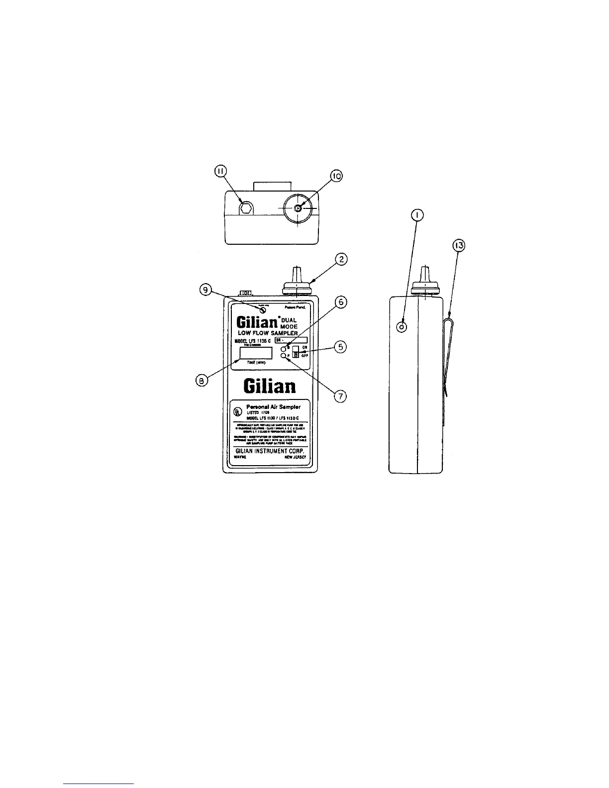
1. Charging Jack
2. Inlet Filter Assy.
5. On/Off Switch
6. Battery Check Indicator
7. Fault Indicator
8 Clock Display
9. Flow Control Valve
10. Inlet Boss
11. Outlet Port/Cap
13. Belt Clip
Figure 2
LFS-113 Air Sampler
General Description, front, side & top
page 14
scheduled to be used for long periods of time, (more than 2 months), it is recommended that the
following procedure be followed on a periodic basis.
a) Run pumps until they shut down on low battery.
b) Recharge the battery overnight (16) hours and return the pumps into storage.
5.2 Replacing the Battery: (refer to figure 7)
Place the sampler face down on a soft, level surface. Remove the four corner case screws.
Supporting the pump by the front half, turn the sampler face up. Remove the top half to reveal
the internal mechanism.Disengage the Battery Connector from the receptacle located on the
Control Board (13 or 14). Lift the battery pack (9) from the base of the case. To install a new
battery, reverse this procedure. NOTE:The connector is polarized and can only be properly
installed in one direction.
5.3 Changing the Pump Filter: (refer to figures 2 and 7)
Under normal operating conditions, the pump filter should be changed after approximately
250 hours of operation or when needed. Failure to change the filter as it becomes dirty will
decrease the pump's back pressure capability and performance envelope.
Blow all dust and debris from around the Filter Housing (2). Grasp the knurled edge of the
filter housing assembly and rotate counter-clockwise. Check the new filter housing assembly to
make sure that the sealing "O" ring is present on the internal boss. Install the new Filter Housing
Assembly onto the pump rotating the knurled edge clockwise. Do Not Overtighten! Check the
filter’s performance by using the Constant Pressure Check,
(see Section 4.2.1).
 Loading...