page 9
2.0 OPERATION SET-UP
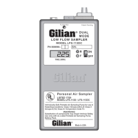
2.1 Charging the LFS-113: (refer to figures 2 and 3)
Plug a Gilian dual-rate charger into a properly grounded AC outlet. Set the charging rate
select switch to the "Normal" mode.Insert the charging jack into the sampler's Charging
Receptacle (1), located on the side of the pump.Upon insertion, the "Normal" rate LED on the
charger will light indicating active charging of the battery pack.
Charge the battery for a minimum of 16 hours at the "Normal" rate.After 16 hours the
sampler may be removed from the charger and utilized.If the sampler must remain on charge
for longer than 16 hours, the charger should be switched over to the "Trickle" charge
mode.Charging in accord with the above instructions will prolong battery life.Failure to follow
these instructions may cause deterioration and permanent damage to the battery pack.
2.2 Filter Check:
Make sure that the Inlet Filter Assembly (2) is secured into the suction Inlet Boss (10). Check
this by rotating the knurl on the bottom of the Filter Assembly clockwise. Do Not Overtighten.
3.0 Operation
The LFS-113 is a dual mode sampler, providing low flow air sampling in Constant Flow
or Constant Pressure (multiple flow) modes. In the "Constant-flow mode, the unit is externally
set from 5-200 cc/min. by adjustment of the Flow Control Valve (9). In the "Constant-pressure"
mode, the unit is externally set from 1-350 cc/min.by means of the Flow Controller Valve(s)
within the Flow Controller Tube Holder Assembly.
A green Battery Check LED Indicator (6) lights to show that the battery will run for a
minimum of eight (8) hours at any flow regime within the unit’s capability.A red Flow Fault
LED Indicator (7) is actuated by either a blocked inlet condition or insufficient battery voltage
to maintain the preset flow.
3.1 Mode Selection:
The Mode Selector Switch (4) is located on the back of the sampler, adjacent to the top of
the Belt Clip.This unlocks, indexes and re-locks the Mode Selector Valve into one of the Dual
sampling modes.
The Mode Indicator (3) is observable through a hole in the side of the case.If the indicator
is black, then the unit is in the "Constant-Flow" mode. If the indicator is light or white, then the
unit is in the "Constant-Pressure" mode (multi-flow sampling).
To set the LFS pump into one of the sampling modes, insert the Allen Key, ("L"-shaped hex
wrench) provided with the sampler, into the Mode Selector Switch (4).Rotate the key counter-
clockwise to unlock the rotor. Continue rotating the key counter-clockwise approximately one
half a turn until the switch clicks in.
page 12
cannot exceed 350 cc/min. After the flow of each position has been set, check that no flow
interactions have occurred. If there has been a deviation at one particular position, go back to
each cassette and readjust the flow.
The unit can now be removed from the rotameter and prepared for sampling. In the
"Constant-pressure" mode, blocking any one or all of the sorbent tube inlets, will not cause the
sampler to flow fault.However, if the battery voltage falls below the operating point required,
the Fault Indicator (7) will light and the unit will cease running.
4.0 PERFORMANCE CHECKS
4.1 Constant Flow Performance Check
Make sure that the pump is in the "Constant-flow mode, (refer to Section 3.1for complete
mode selection procedure).A simple method of quickly checking constant flow performance is
provided by Gilian's Low Flow Industrial Hygiene Calibrator Pack (LIHCP).
Attach the pump into the LIHCP or similar calibration set-up, (see figure 6). If you are using
the LIHCP calibrator: open the shut off valve (V1). Turn the sampler ON. Adjust the sampler
flow by inserting a small blade screwdriver into the pump's recess marked Flow Adjust (9).
Engage the blade of the screwdriver with the slot of the Flow Control Valve and slowly rotate
the valve clockwise to decrease flow or counter-
clockwise to increase flow.Observe the reading on the rotameter.If a precision reading is
required, a film flowmeter must be used.
Close shut-off valve (V1) and adjust load valve (V2) to 20" H
2
O. Allow sufficient time for
the flow to reach stability. NOTE:If very low flows are being used, please allow several minutes
time for stabilization.Check the reading on the rotameter or the film flowmeter if one is being
used..Accuracy can be determined by taking the difference in flows over the original set
point.The deviation should be less than 5%.Reopening the shut-off valves allows rechecking
the initial set point.
4.1.1 Pressure Fault Check:
Using the same test set up as shown in figure 6, adjust load valve (V2) so that the pressure
on the magnehelic gauge (P1) exceeds 25-30" H
2
O. After 3-5 minutes the Fault Indicator (7) will
light indicating an excessive pressure condition. Approximately 20 to 40 seconds later, the unit
will cease running and the time will be latched and indicated on the Clock Display (8) - (DC
models only). The fault can be cleared and re-set (opening the load valve) by turning the Power
Switch OFF and then back ON again.
4.1.2 Pressure Fault Clear Check:
Adjust load valve (V2) again so that the pressure exceeds 25-30" H
2
O. The Fault
indicator will light, indicating an excessive pressure condition. Slowly reduce the load
pressure. The Fault Light will extinguish at a pressure below 20" H
2
O and the pump will
continue to operate normally.
 Loading...