However, be sure to check for damaged parts, loose
nuts and bolts, especially ground wires which could
have occurred in transit.
GROUND: All portable generators must be grounded.
The ground terminal on the generating set should
always be used to connect the set to a suitable ground.
The ground path should be #8 size wire, connected to a
1” copper pipe or steel rod, penetrating into the ground
approximately 10”. Connect copper ground clamp to
the pipe and connect a #8 AWG between this clamp
and the gen-set negative ground clamp.
LOCATE AND BE FAMILIAR WITH THE
FOLLOWING ITEMS ON RECEPTACLE
PANEL FOR SINGLE CYLINDER GEN-SET
AND RECEPTACLE PANEL ON V-TWIN
GEN-SET.
Most generator sets will have a receptacle panel with a
variety of components, depending on the specific
generator set. It is important to know that all
receptacles conform to National Electrical
Manufacturer's Association (NEMA) regulations and
matching NEMA male caps should always be used.
Always use grounded male plugs. The neutral line of
generating set is mechanically grounded to frame.
CIRCUIT BREAKER: All portable single phase
generating sets have automatic trip, circuit breakers to
protect against electrical overloads. If possible, it is
advised to switch off or remove electric load before
starting engine.
BALANCED LOAD: This exclusive and patented
special winding design will automatically not allow an
unbalanced electric load condition while using a large
120 volt load, thereby allowing full KW generator power
on any 120 or 240 volt receptacle.
ENGINE STOP SWITCH: Some models have the
engine stop switch on the receptacle panel and some
models have this stop switch located on the engine.
Always locate this switch and be familiar with its
location before operating the set.
HOUR METER: All GPE models indicate the hours of
use to help in determining service periods. This
particular generator has the following features:
1) HOUR METER: Calculates and totals the entire
running time of gen-set. This is particularly helpful in
determining service periods of the engine.
2) TACHOMETER: This meter is part of the hourmeter
and is functional when small push button on hourmeter
housing is depressed. It calculates and displays the
speed of gen-set, which is set at 3750 RPM, at no
load. NOTE: There is no voltmeter on operator’s
panel to determine voltage output, due to short life of
meter mechanism undergoing normal engine
vibration. However, the engine speed set at 3750
RPM equates to 125/250 volts at no load.
3) TWO SERVICE ALERTS: At each 25 hour run
time of engine, the service alert “CHG OIL & FILTER”
AND “SVC ENG AIR CLEANER” will appear on the
tachometer.
4) There is a mode button on meter bezel of
tachometer, that allows repair/operator to scan the
various alerts (hourmeter, tachometer, and (2)
service alerts). Simply press the mode button for
each topic of information. Once service is complete,
the mode button should be pressed to show the
tachometer reading. The engine speed should be
adjusted to run at no load, 3750 RPM. This speed
equates to the correct generator voltage of 125/250
at 61-62 hertz, and replaces the need of the short
lived voltmeter.
Page 4
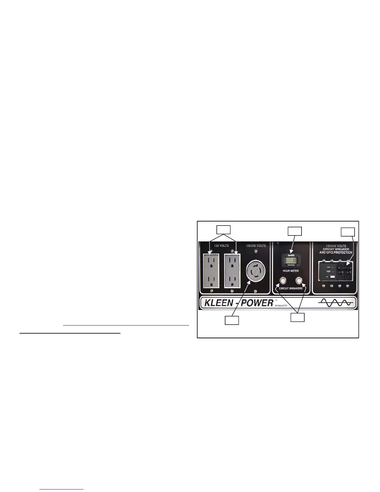
1) STANDARD 120 VOLT, 15 AMP, NEMA 5-15R RECEPTACLE
2) STANDARD 120/240 VOLT 20 OR 30 AMP NEMA L14-20R OR
NEMA L14-30R TWIST-LOCK, 4 WIRE RECEPTACLE.
3) PUSH BUTTON, THERMO RE-ACTING MAIN CIRCUIT BREAKER
4) TWO POLE MAGNETIC RE-ACTING MAIN CIRCUIT BREAKER
WITH BUILT-IN GFCI PROTECTION (See note below).
5) RUN TIME METER
NOTE: GILLETTE EXCLUSIVE, COMBINATION MAIN LINE CIRCUIT
BREAKER AND GROUND FAULT CIRCUIT INTERRUPTER, BUILT
INTO ONE PIECE CONSTRUCTION. SEE PAGE 10 FOR ADDI-
TIONAL GFCI INFORMATION.
GEN-SET PANEL FOR 5.5 THRU 7.5 KW
#1
#2
#3
#5
#4
 Loading...