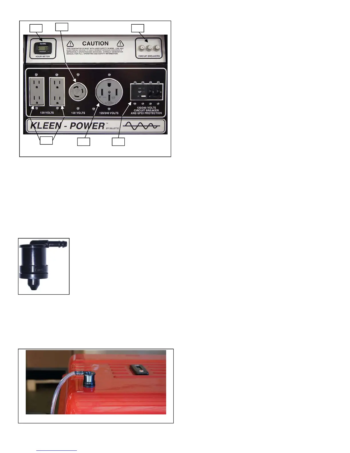
SLOSHING VALVE: EPA requires a device that
captures fuel tank fumes (not
allowing fumes to escape into the
atmosphere) and direct them to the
engine air cleaner. This valve is
mounted on top of gen-set fuel tank,
where excess gasoline fumes
accumulate. Occasionally, when gen
-set is transported, the fuel can
“slosh” and actually enter into the air cleaner. This
“sloshing” valve prevents the passage of fuel fluids
while allowing vapors to proceed to the engine air
cleaner. The valve is made of plastic and may be
vulnerable to breakage in construction applications.
The engine protective cover will help protect this valve
from destruction.
CAUTION: If fuel tank is filled completely full, beyond
the “full fuel line”, or if air vent hose is “kinked” shut,
or if gen-set is operated on a severe slant, the fuel
tank venting is stopped. Under this condition, the non
-venting of fuel tank may cause internal pressures
that can actually collapse the fuel tank, beyond
repair.
FUEL VALVE: The generator fuel tank has an ON-
OFF valve and filter screen system mounted
underneath tank. Always keep this valve closed
when the set is not in use, or in transit.
FUEL GAUGE: All models have fuel level indicator
built into the extended run fuel tanks. You can always
safely monitor fuel level on all tanks without cap
removal.
FUEL CAP: Fuel cap should be opened only when
refueling the tank. When replacing the cap, be sure
to turn cap clockwise until cap locks in place.
OIL-GUARD: All models have protection against
damage to engine resulting from low oil level. As the
oil level falls below safe level, the engine
automatically shuts down and the engine will not
restart, until oil is added. Continually, check the oil
level dip stick on engine, to avoid this situation.
6. LOAD APPLICATION:
Determine the total electric load before it is
connected to generating set to prevent overloading.
Always compare the generating set nameplate data
with that of the equipment to be powered by the
generator set to insure that watts, volts, amperage
and frequency requirements are suitable for operating
equipment. Generally, the wattage listed on the
equipment nameplate is its rated output. However,
some equipment may require three to ten times more
wattage than its rating on the nameplate, as the
wattage is influenced by the “plugged-in” equipment
efficiency, power factor and starting system. NOTE;
If wattage is not given on equipment nameplate,
approximate wattage may be determined by
multiplying nameplate voltage by nameplate
amperage, as found on the “plugged in” equipment.
VOLTAGE X AMPERAGE = WATTS
When connecting a resistive load such as
incandescent lights, heaters or common electric
power tools, a capacity of up to the generating set full
rated wattage output can be used. When connecting
a fluorescent or mercury light, transformers, inductive
coils, or electric motors a capacity of up to the
generating set full rated wattage output, multiplied by
0.6 can be used.
Page 5
FUEL TANK “SLOSHING” VALVE INSTALLED
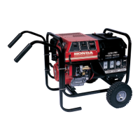
GEN-SET PANEL FOR 9.5 THRU 15.0 KW
#1 #2
#3
#5
#4
#6
1) RUN TIME METER
2) INDIVIDUAL PUSH BUTTON CIRCUIT BREAKERS
3) NEMA 5-20R, 120 VOLY DUPLEX RECEPTACLES
4) STANDARD 120 VOLT, 30 AMP TWIST-LOCK RECEPTACLE
5) STANDARD 120/240 VOLT, STRAIGHT BLADE RECEPTACLE
6) TWO POLE MAGNETIC RE-ACTING MAIN CIRCUIT BREAKER
WITH BUILT-IN GFCI PROTECTION (See note below).
NOTE: GILLETTE EXCLUSIVE, COMBINATION MAIN LINE CIRCUIT
BREAKER AND GROUND FAULT CIRCUIT INTERRUPTER, BUILT INTO
ONE PIECE CONSTRUCTION. SEE PAGE 10 FOR ADDITIONAL GFCI
INFORMATION.
SLOSHING
VALVE
 Loading...