EasyManua.ls Logo

GJD DygiZone User Manual

GJD DygiZone
7 pages
To Next Page IconTo Next Page
Page #1 background imageLoading...
Page #1 background image
DygiZone
GJD910 Advanced Multi-function, 4 zone, security lighting
controller and enunciator
INTRODUCTION
The DygiZone 4 zone security lighting controller works in
conjunction with GJD’s 4 Zone Expansion Unit and range
of external detectors.
PACKAGE CONTENTS
1 x DygiZone 4 zone security lighting controller
2 x xing screws
2 x wall plugs
1 x installation guide
POWERING UP THE DYGIZONE
After powering up the DygiZone controller with the battery
removed:
Each zone’s status LEDs (red, yellow and green)
and blue zone buttons will ash
All LCDs icons will display on the screen
When installation is completed removing the backup
battery tab will enable the clock to keep running in the
event of power loss
NOTE: Press any button to clear the display.
Alternatively, the display will clear automatically after
1 minute.
When the display clears, and if nothing is activated:
The LCD displays the clock time (automatically
defaults to 00:00 if the battery is not connected)
The symbol M appears on the DygiZone which is
congured as the master controller.
Note: The letter M does not appear when setting up a
DygiZone as a slave controller.
Each zone’s status LEDs will display the zone’s
current programme state.
Note: The factory default setting is audible and
automatic for all active zones (red and green status
LEDs illuminated).
ZONE INDICATOR ICONS
For each of the 4 zones there are a set of sub-zone icons
that appear above the respective zone’s status LEDs.
Note: These icons will not be displayed until a detector
on the system has triggered.
When a detector connected to the A1, A2 or A3 input of the
Expansion Unit is triggered:
The LCD will display the numbers 1,2 and 3 above
the respective zone number.
A circle will appear around the number that
corresponds to the detector that has been triggered.
The corresponding zone’s button will illuminate.
Note: The numbers 1, 2 and 3 correspond to the
Expansion unit inputs A1, A2 and A3 respectively.
Upon activation the circle will ash for 8 seconds and then
will remain visible for a time duration equal to the setting
of TIME MINS in the engineer programming. The numbers
1, 2 and 3 will also be visible for this time but will not ash.
Once this time has elapsed, all the icons will clear from the
LCD.
ZONE MODES & STATUS INDICATORS
Audible Mode: Beep or voice mode is activated and will
sound on detector activation.
Status Icon: Musical note icon for either voice
or beep more. The microphone icon is only
visible if voice mode is selected.
Status LED: Red, constantly lit.
Automatic Mode: Works in conjunction with the photocells
in the detectors. The external security lights will only be
activated if it is dark, thereby saving energy.
Status Icon: Stick gure icon
Status LED: Green, constantly lit LED
indicates mode selected.
Yellow LED illuminates when the external
lighting is activated.
Manual Override Mode: The external security light will
now remain on irrespective of detector status - useful for
barbecues or when working outside in the dark for long
periods.
Status Icon: Light bulb icon
Status LED: Yellow, lit during light activation
period.
Time Mode: External security lights will be illuminated as
per the TIME 1 or Timer 2 options.
Status Icon: Light bulb icon
Status LED: Yellow, lit during light activation
period.
Note: Zone status icons are only visible when the
respective zone button is pushed. The icons are
located in the top-centre of the LCD display.
INDIVIDUALLY SETTING ZONES
Each zone can be individually congured from the keypad
by cycling through the available modes.
The conguration process is as follows:
Press the button for zone you would like to congure.
The zone’s status LEDs and icons will be displayed.
Press the button again to cycle through the different
modes available until the desired mode is reached.

Other manuals for GJD DygiZone

Question and Answer IconNeed help?

Do you have a question about the GJD DygiZone and is the answer not in the manual?

GJD DygiZone Specifications

General IconGeneral
Zones Supported4
Communication ProtocolRS485
Weight300g
IP RatingIP20
TypeController
Input Voltage24V DC
Output Voltage24V DC
ProtectionShort Circuit
Enclosure MaterialPlastic

Summary

DygiZone Introduction and Package

Introduction to DygiZone Controller

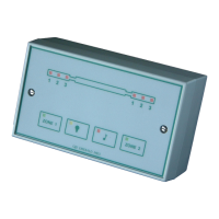
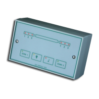
Overview of the DygiZone 4 zone security lighting controller's function with expansion units.

DygiZone Package Contents

Lists the essential items included in the DygiZone controller package.

Powering Up and Initial Display

DygiZone Power-Up Sequence

Details the initial status LEDs and LCD display behavior upon powering up the DygiZone.

Zone Status and Indicators

Zone Indicator Icons

Describes the sub-zone icons appearing above status LEDs when a detector triggers.

DygiZone Zone Modes

Explains various zone modes like Audible, Automatic, Manual Override, and Time modes with their indicators.

Individually Setting Zones

Configuring DygiZone Zones

Outlines the process for individually configuring each zone's mode from the keypad.

Detection Information Display

LED and Text Indicators

Explains PIR text, blue LCD backlight, and text display duration during detection events.

Recording Voice Messages

How to Record a Voice Message

Step-by-step guide on recording custom voice messages for zone activation alerts.

Engineer Programming

DygiZone Programming Process

Details the procedure for accessing and adjusting settings via engineer programming mode.

Zone Configuration and Settings

Selecting Active Zones

Describes how to select and configure the number of active zones for the DygiZone system.

Setting Light Activation Time

Explains how to set the duration for which lights remain active after detection.

Detector Sensitivity and Modes

Setting Detector Sensitivity

Adjusts the number of detector triggers (pulse count) required for activation.

DygiZone Mode Settings

Details the five programmable modes (1-5) for each zone's operation.

TSEC Output and Clock Settings

TSEC Output Duration

Sets the duration (1-30 seconds) for the 12V positive switched signal from the TSEC output.

Setting Clock Display Format

Configures the clock display format to 12-hour, 24-hour, or OFF.

Setting the Clock Time

Procedure for setting the internal clock time on the DygiZone.

Walk Test and Timed Operations

DygiZone Walk Test Mode

Enables testing of detectors by activating audible beeps and displaying zone/PIR information.

Pre-set Light On/Off Times

Allows programming of specific times for automatic external light activation and deactivation.

Keypad Lock and Defaults

Locking the DygiZone Keypad

Prevents accidental program or setting changes by locking the keypad.

Restoring Default Settings

Procedure to return the DygiZone to its original factory default settings.

Power Up Reset and Slaves

DygiZone Power Up Reset

Instructions for performing a hard reset by removing the backup battery and power.

DygiZone Slave Controllers

Explains how to connect and configure additional DygiZone units as slave controllers.

Maintenance and Specifications

DygiZone Maintenance Mode

Indicates keypad lock status and if supply voltage is outside specification.

DygiZone Technical Specifications

Provides key technical details including supply, display, audio, control, and certifications.

Displays and Controls Overview

DygiZone LCD Display Elements

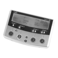
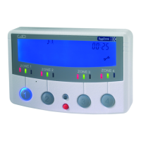
Details the various indicators and information shown on the DygiZone LCD screen.

DygiZone Control Buttons

Identifies the functions of the zone buttons, microphone, red button, and up button.

Wiring Diagram

4 Zone Expansion Unit Wiring

Illustrates the wiring connections for the 4 Zone Expansion Unit and DygiZone controllers.

Internal Components and Adjustments

DygiZone PCB Components

Highlights key components and adjustment points on the DygiZone printed circuit board.

Volume and Backlight Adjustment

Details how to adjust the internal speaker volume and LCD backlight brightness.

Related product manuals