8.0 FLUE OPTIONS
8.5 Kit C Horizontal Anti-Plume Flue Kit
(C13) - Part No. 956084
If the standard horizontal terminal is likely to cause nuisance to
a neighbour or buildings, because of excess pluming, then this
particular flue kit raises the flue gas outlet point to a higher
elevation with the minimum amount of changes. The flue gas
duct is teed-off from the concentric part and covered by an
80mm outer tube to protect the flue duct from freezing. The
air in-take remains at the lower level (see Fig. 24).
If choosing this option then the external flue duct length
should be taken into account when calculating equivalent flue
length.
For installation details refer to the flue kit instructions.
Dimensions from vertical terminals to opening windows should
be in line with Fig. 19.
(For use with Standard horizontal telescopic flue kit - Part no.
956120 - only).
This kit is provided to assist in fitting a condensing boiler with
reduced clearances when fitted in good practice according to
the Guide to Condensing Boiler Installation published by
DEFRA/HMSO.
This kit allows the boiler f
lue outlet to be directed to the left
or to the right only.
Suitable for installations if the appliance cannot be repositioned
and where other horizontal flue options may cause some
nuisance to neighbours or buildings. The flue kit contains some
additional 45° elbows and extension ducts as well as a special
wall bracket to pass the guttering (see Fig. 26). The concentric
flue will be routed vertically alongside the outside wall to
above the roofline. Special seals are required to prevent
rainwater penetrating the pipe joints.
For installation details refer to the flue kit instructions.
8.6 Plume Diverter Terminal Kit
Part No. 956103
8.7 Kit D External Vertical Flue
(C33) - Part no. 956085
93 flanged elbow (concentric)
with sampling point
Raised external flue outlet kit -
Part no. 956084
Kit C
Raised Ø60mm flue
outlet duct with
Ø80mm anti-freeze
pipe.
Max height of raised
flue from top of boiler
to centre of outlet 8.5m
Min height 1m.
Standard horizontal flue
adaptor has an already
built-in fall in the flue to
allow the condensate to
drain away.
93 flanged elbow (concentric)
with sampling point
Max. lengths (from top of
boiler to AIR COWL 8m
Min. length 1m.
Kit D
Ø60/100mm concentric
air/flue pipe -
Part no. 956093
(1m extension)
and
Part no, 956092
(0.5m extension)
For outside installations
the pipe joints have to
be covered with special
“lip-seal” to prevent
rain ingress.
Ensure all horizontally fitted
pipes are routed with a
2.5-3° fall towards the boiler.
External vertical flue kit - Part no. 956085
Roof terminal
with rain cover.
Roof terminal
with rain cover
and pitched roof
flashing kit.
b
a
8.4 Offset Vertical Flue Terminal
(C33) - HBL Part 956081
‘a’ measured from boiler flue outlet centre line to the centre
line of the extension elbow.
‘b’ measured from the top of the boiler to the underside of the
air cowl.
Maximum allowable length of a + b = 8900mm
Fig. 23
Fig. 24
Fig. 25
Fig. 26
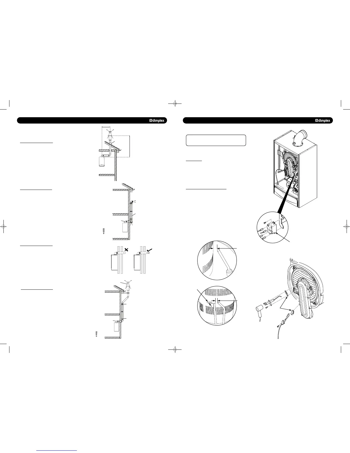
13.0 CHANGING COMPONENTS
IMPORTANT:
When changing components ensure that both
the gas and electrical supplies to the boiler are isolated
before any work is started.
See Section 12 : “Annual Servicing” for removal of case, panel,
door etc.
© Dimplex Boilers 2008
1. Disconnect the two feed wires, earth wire and electrode
lead noting their positions (Fig. 53).
2. Undo the two screws securing the igniter to its bracket and
remove the igniter. Reassemble in reverse order.
13.2 SPARK AND SENSING ELECTRODES
1. Disconnect the electrode leads, noting their positions
(Fig. 56).
2. Using a 3mm Hex key, remove the retaining screws securing
each of the electrodes to the burner door and remove the
electrodes.
3. Check the condition of the sealing gaskets and replace if
necessary. Reassemble in reverse order and then check that
the electrode gaps are as shown in Fig. 54 & 55.
Fig. 53
Fig. 54
Fig. 55
Fig. 56
Igniter
Gasket
6mm ± 0.5
to Burner
4mm ± 0.5
10mm ± 0.5
751262 MANUAL 19/10/10 08:41 Page 18
 Loading...

