9.0 INSTALLATION
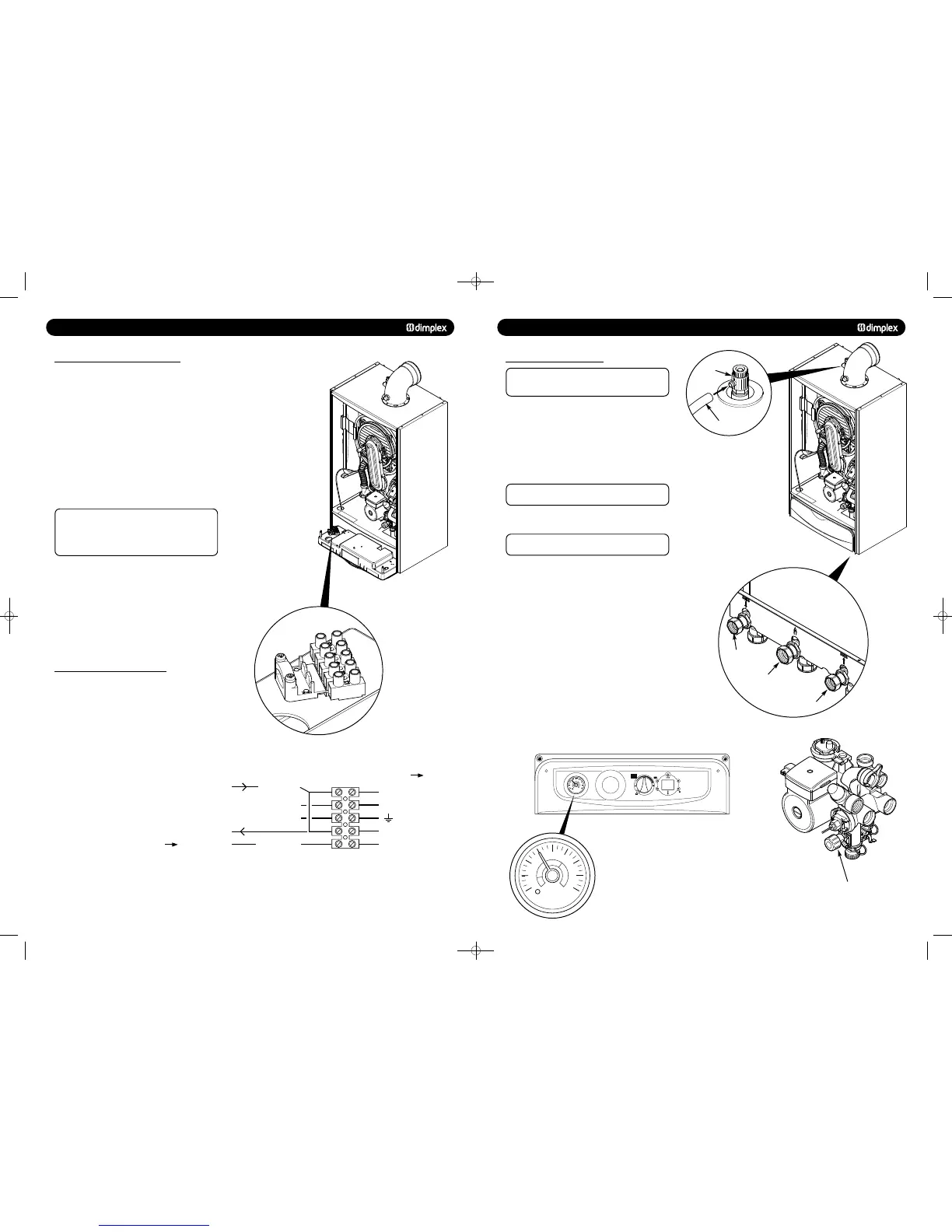
9.6 MAKING THE ELECTRICAL CONNECTIONS
The boiler is fitted with a 1.5m length of 3 core cable. This
can be connected to the fused 3A 230V 50Hz supply.
To connect an external control proceed as follows:-
1. Lower the drop down door.
2. Remove the two screws holding the controls box and ease
the box away from the boiler. The electrical connections are
made at the left hand side on the rear of this box.
3. Slacken the cable clamp on the terminal block (Fig. 36).
Insert the external control wiring through the clamp and route
it to the terminal block. Tighten the cable clamp.
4. Refer to the instructions supplied with the control.
be suitable for
230V switching.
Ensure that the external control input cable (s) have
sufficient slack to allow the control box to drop down.
5. Route external control cables away through the mains cable
grommet supplied.
9.7 PRELIMINARY ELECTRICAL CHECKS
1. Prior to commissioning the boiler preliminary electrical
system checks should be carried out.
2. These should be performed using a suitable meter, and
include checks for Earth Continuity, Resistance to Earth, Short
Circuit and Polarity.
L1 brown
L2 red
green/yellow
green/yellow (earth)
Fused supply 3A
230V~50Hz
brown (live)
red linkwire230V - Switch Live
230V - To external control
Permanent live
blue (neutral)
N blue
L3 orange
Connect external control using L2 & L3
Disconnect link wire
To boiler
10.0 COMMISSIONING
10.1 COMMISSIONING THE BOILER
IMPORTANT: The air vent on top of the boiler must be
OPEN when filling
the system. Attach a tube to the air vent
to safely collect any excess water (Fig. 38).
Gas Soundnes
1. Ensure the gas service cock on the boiler is turned on
(Fig. 40). The entire gas installation must be tested for gas
tightness and purged in accordance with BS6891.
2. Open the service cocks to the CH flow and CH return
supplies.
3. Connect the filling loop and fill and vent the CH system.
Ensure the boiler is completely vented using the
manual air vent on top of the boiler.
4. Drain, flush and refill the boiler and system in accordance
with BS7593 (Fig. 30).
Failure to flush the system and to add inhibitor will
invalidate the appliance warranty.
5. Pressurise the system to 1.5 bar (Fig. 42).
Electrical Safety Checks on the Controls System
and Boiler
6. Carry out earth continuity, resistance to earth, short circuit
and polarity checks using a suitable meter.
7. Switch on the electricity supply to the boiler.
8. Set the controls to call for heat. The boiler will now operate.
Check the system for correct operation.
9. Replace the outer door and two securing screws.
© Dimplex Boilers 2008
Fig. 39
Fig. 38
Fig. 40
Fig. 41
Fig. 42
Fig. 43
CH Return
CH Flow
Gas Inlet
Boiler Drain Point
0
1
2
bar
3
4
751262 MANUAL 19/10/10 08:41 Page 24