13.0 CHANGING COMPONENTS
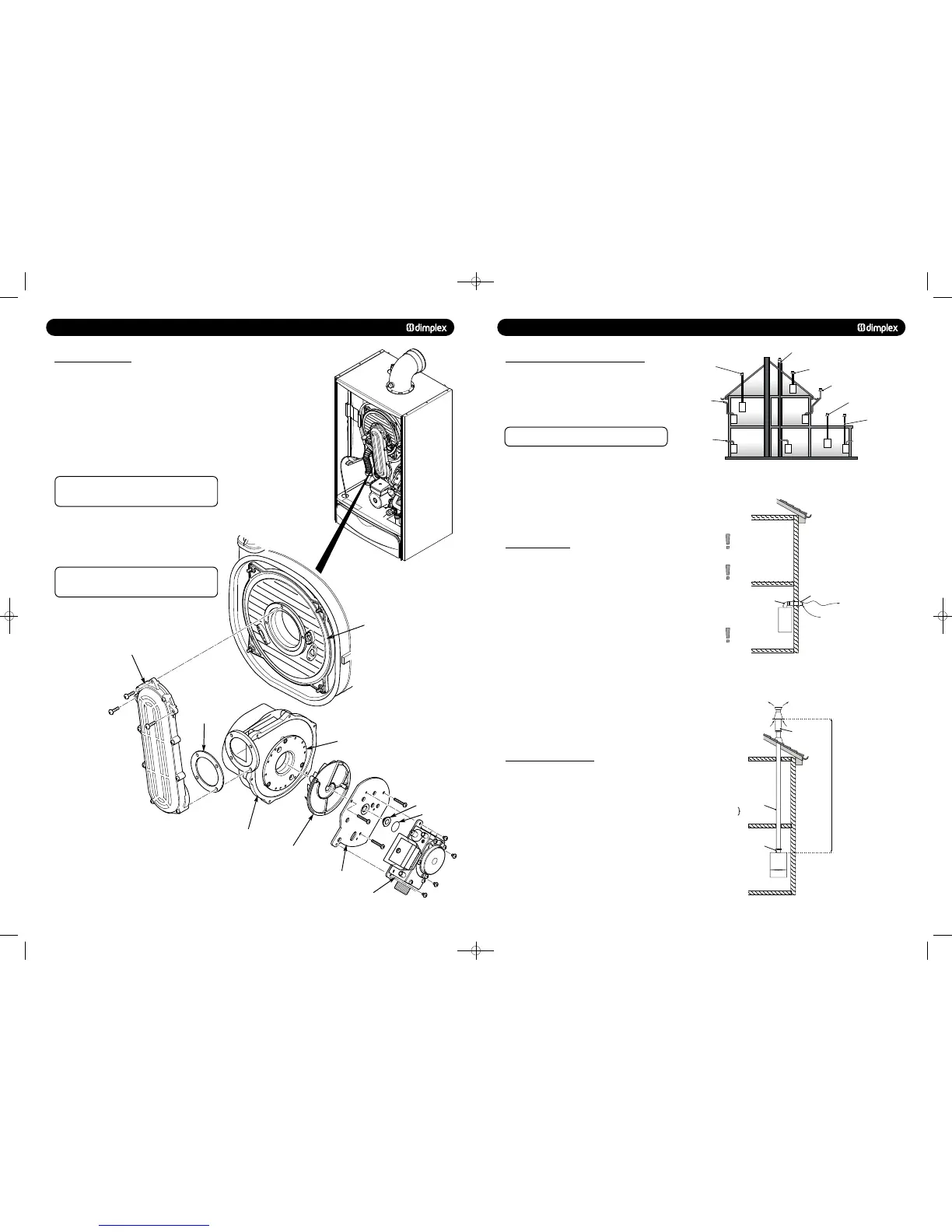
13.3 GAS VALVE AND FAN
1. Disconnect the two leads to the fan and one lead to the gas
valve.
2. Undo the nut on the gas inlet pipe to the valve and retain
the sealing washer.
3. Remove the three securing screws holding the air/gas
Channel to the burner door plate and remove the valve and fan
assembly (Fig. 57).
4. Remove the three screws holding the valve and swirl plate
to the fan adaptor plate.
Mark on the adaptor plate which holes are being
used by the screws. Using the wrong holes on
re-assembly will cause mis-alignment of the gas valve.
6. Remove the three screws holding the fan adaptor to the fan.
7. Remove the four screws securing the fan to the air/gas
channel. Reassemble in reverse order ensuring all seals are in
place.
The gas valve throttle should be adjusted in
accordance with the instructions supplied in the spares kit
See Section 10.
Swirl Plate
Fan
Fan Gasket
Burner Door
Air/Gas Channel
Fan Adaptor Plate
Injector Plate
Injector
Injector ‘O’ Ring
Gas Valve
8.0 FLUE OPTIONS
8.1 CONCENTRIC AIR/FLUE DUCT SPECIFICATIONS
The Dimplex System 18 & Dimplex System 30 boilers can be
installed to a number of different concentric flue systems. The
different flue applications as shown in Fig. 20 are available as
kits comprising the connecting parts to the appliance and end
terminal. Flue extension ducts and extension elbows are
available as accessories.
Dimplex System 18 only, with maximum concentric
flue length of 10m, the heat input will be reduced by 7.6%
© Dimplex Boilers 2008
17
8.2 Kit A + Telescopic Horizontal Wall Terminal
(C13) - Part No. 956120
Traditional concentric flue system, Fig. 21, with a maximum
length of 10000mm. The flanged flue elbow is designed with a
3° slope towards the appliance so that the condensate can
easily drain off. It has to be considered that for every metre
horizontal flue length the terminal exit centreline is approx.
45 mm higher than the elbow’s centreline.
The standard telescopic terminal is 615mm max length and
430mm min length, but can be cut to a minimum flue length of
250mm, which is suitable for single, 100mm (4”), brick walls.
8.3 Kit B Vertical Concentric Flue Terminal
(C33) - HBL Part 956081
Standard concentric (100/60) vertical flue application, Fig. 22,
through roof attics with a maximum length of 12000mm.
The kit comprises of the roof terminal, flashing kit, vertical
adaptor with sampling point and bracket.
The maximum length is measured from the top of the
appliance casing to the underside of the air cowl.
For installation details refer to the flue kit instructions.
Chimney flue liner kit
- Part no. 956082
Vertical flue kit - Part no. 956081
Vertical flue kit - Part no. 956081
with flat roof flashing plate
Split pipe vertical flue outlet kit
- Part no. 956080
with flat roof flashing plate
Raised external flue outlet kit
- Part no. 956084
Vertical flue kit - Part no. 956081
External vertical flue kit
- Part no. 956085
Standard telescopic
horizontal flue kit
- Part no. 956120
Flue system application
The pluming from the flue may
cause nuisance to neighbours
or other buildings.
60/100 flue accessories:
0.5m flue extension duct - 956092
1m flue extension duct - 956093
93 flue extension elbow - 956091
45 flue extension elbow (2x) - 956090
Vertical flue turret - 956087
Ø60/100mm concentric
standard horizontal wall
terminal.
Max. length 10,000mm.
Min. length 250mm.
Standard telescopic horizontal flue kit - Part no. 956120
Horizontal terminal has a
built-in fall in the flue to allow
condensate to drain away.
If horizontal flue requires
extension pipe. the flue
should be installed such
that there is no section less than
2.5° - 3° to the horizontal,
falling back towards the boiler.
93 flanged elbow (concentric)
with sampling point
Kit A +
Vertical flue kit - Part no. 956081
Suitable for 25 - 45°
Pitch Angle
Length
Kit B
60/100 flue accessories:
0.5m flue extension duct - 956092
1m flue extension duct - 956093
93 flue extension elbow - 956091
45 flue extension elbow (2x) - 956090
Flat roof flashing plate - 840512
93 flanged flue elbow - 956086
Max. length12m.
Min. length 0.6m.
Roof terminal
with rain cover
and pitched roof
flashing kit.
Vertical flue socket
with sampling point.
Top of Boiler
to underside of Cowl
751262 MANUAL 19/10/10 08:41 Page 17
 Loading...

