Do you have a question about the Glendinning Cablemaster and is the answer not in the manual?
Guidance on selecting the best mounting location for the power unit and ensuring adequate cable storage space.
Considerations for practical hawse pipe placement and power cord exit point on the boat.
Instructions for wiring the Cablemaster to the boat's DC electrical system, including safety precautions.
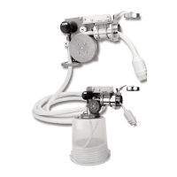
Describes the recommended direct mounting of the power unit above the storage container.
Explains how to mount the power unit away from the hawse pipe using extensions for space constraints.
Details the process of routing the cable vertically through the deck using pipe extensions.
Covers various mounting arrangements and directing the cable using PVC pipe and angle connectors.
Steps for marking the correct position for the hawse pipe, checking for obstructions.
Instructions for drilling and securely mounting the hawse pipe to the boat's hull.
Guidance on attaching the power unit to the hawse pipe, including remote installations.
Detailed steps for connecting the Cablemaster to the boat's DC electrical system, including limit switch relocation.
Specific wiring instructions for the CM-4 model using a barrier strip assembly.
Wiring instructions for CM-7 and CM-8 models using an integral relay assembly.
| Category | Marine Equipment |
|---|---|
| Drive System | Electric Motor |
| Voltage | 120V/240V |
| Current Rating | 30A/50A |
| Cable Type | Shore power cable |
| Cable Capacity | Varies by model |
| Control | Remote Control, Local Control |
| Mounting | Deck |
| Material | Stainless Steel |