14
5
INSTALLATION INSTRUCTIONS
The Cablemaster system must be mounted in a loca-
tion that is protected from the marine environment and is certified
“ignition protected” for placement in engine rooms. For ideas on
specific locations for your boat, contact our service engineer.
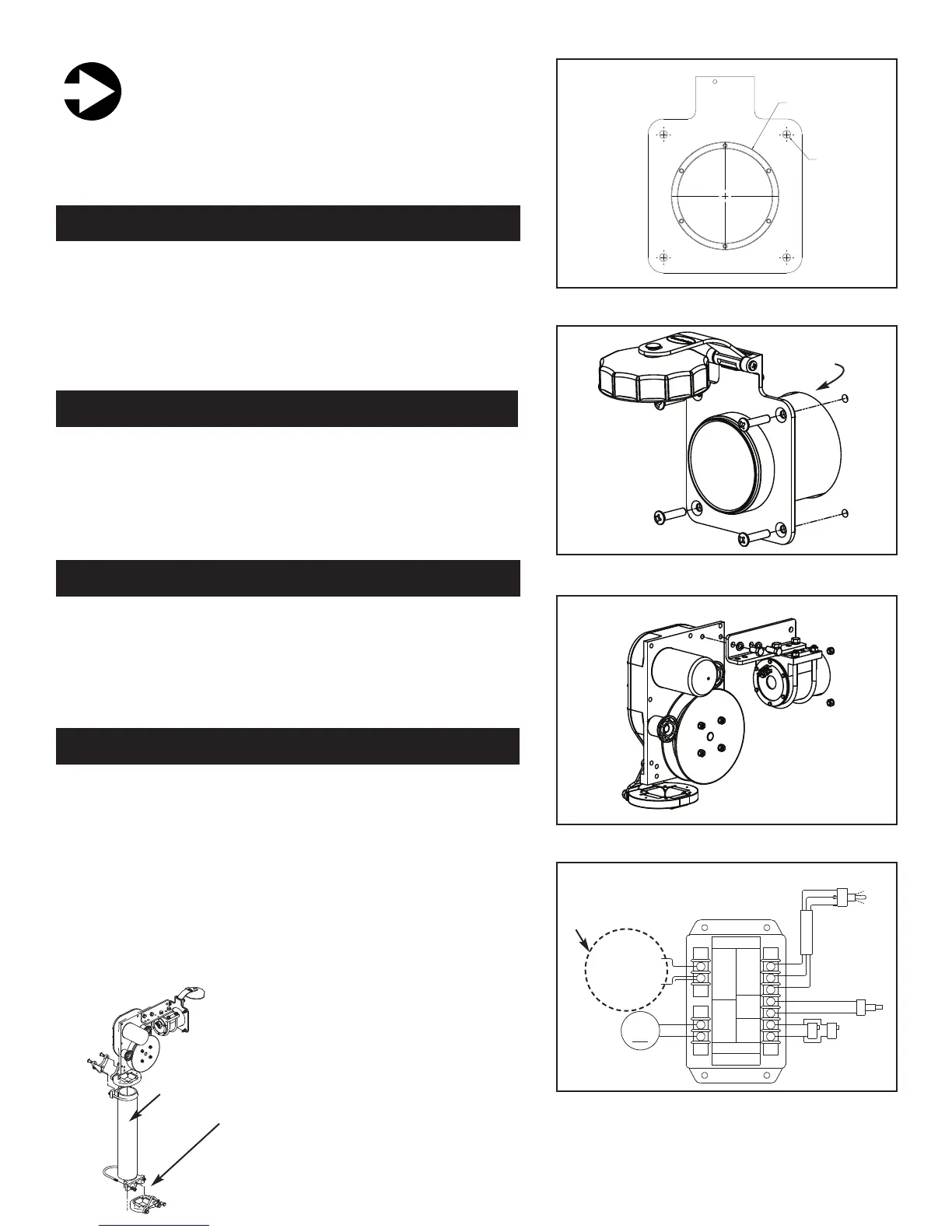
Using the drawing included with your manual, mark the mounting
location of the hawse pipe. Before drilling or cutting, check once
again to be certain that the area behind the hawse pipe is free of
wires, plumbing or structural supports for the boat. The mounting
surface should be a minimum 1/2” thick. The proper thickness can
be achieved by using a butt block of marine grade plywood behind
the mounting surface.
Cut the hawse pipe’s 3-5/8” center hole and drill the four 1/4”
mounting holes. Using a good quality marine beading compound,
secure the hawse pipe to the boat using the four (4) 1/4 x 20 x 1”
stainless steel machine screws, washers, nuts and gasket supplied
with the Cablemaster or use longer fasteners that are available
locally.
The power unit may now be mounted to the hawse pipe using the
angle link, the hawse pipe clamp, and U-bolts. In remote power unit
installations, the 3” schedule 40 PVC pipe is secured to the power
unit using the same standard components adding also the acces-
sories for horizontal pipe extension in order to connect the PVC pipe
to the hawse pipe (see Fig. 3 previous page).
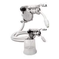
Unless the shore power cable is being directed vertically through
a PVC pipe, you are now ready to wire the Cablemaster to the
boat’s DC electrical system. If the shore power cable is being direct-
ed vertically through PVC pipe (see drawing below) it is necessary
to relocate the guide roller assembly with the out-limit switch from
the bottom of the power unit to the lower end of the PVC pipe. Wires
of appropriate length will have to be spliced into the system to insure
the operation of the out-limit switch. A guide roller assembly without
the out-limit switch, included in the vertical pipe extension accesso-
ry, must be installed between the power unit and the PVC pipe to
provide trouble free operation (see accessory page).
C
HINGE
65002
SPACERS
HAWSE FLANGE70427
HINGE BOLT
74410
ACORN NUT
04800
POWER SWITCH ASSEMBLY
(incl. switch, cover, 3ft. wire)
85414
LIP ROLLER
50416
PULLEY - INSIDE HALF
50417
PULLEY - OUTSIDE HALF
50416
OFFSET PLATE
(included with
04046 assy.)
04046
GUIDE ROLLER ASSEMBLY
(incl. guide, rollers 4X, offset plate)
75412
#9 WOODRUFF KEY
50005
CONNECTOR LINK
50421
HAWSE PIPE CLAMP
04053
HAWSE PIPE CLAMP ASSY.
04050
HAWSE PIPE ASSEMBLY
(incl. hawse pipe with
flange, hinge, cap)
04051
HINGE & CAP ASSEMBLY
50421
HINGE
50420
CAP
RELAY ASSEMBLY
04034 -- 12 / 24 VOLTS
70005
U-BOLT (2X)
65001
Spacer
50415
CHASSIS COVER
50414
CHASSIS
04812
IN-LIMIT SWITCH ASSY.
(incl. switch, 2 ft. wire assy.,
protective boot)
04830
IN-LIMIT SWITCH ASSY.
(incl. hawse pipe ring)
86402
CAP
GASKET
60001
HAWSE
PIPE
RING
86403
HAWSE
PIPE
GASKET
70432
ALLEN SCREW
04824
OUTLIMIT SWITCH ASSEMBLY
(incl. (2) switches, 2 ft. wire assy.)
87404
CHASSIS GASKET
MOTOR ASSEMBLY
(incl. drive gear and
mounting screws)
04035 -- 12 VOLTS
04036 -- 24 VOLTS
86401
HAWSE PIPE
GASKET
04051
CAP & HINGE
ASSEMBLY
90004
POWER
SWITCH
COVER
CableMaster
Model CM7
Parts Diagram
Glendinning Marine Products, Inc.
STEP 1
Use template
on back
cover of
manual
STEP 2
Mount Hawse
pipe in hole
Hole cut in
step 1
STEP 3
Mount Hawse pipe
to power unit
Red 1
White 2
Black 3
Power
Switch
Pos. +
Neg. -
12 / 24v
DC Input
Motor
Output
CABLEMASTER RELAY ASSEMBLY
# 04034 (12, 24 volt DC)
12v DC use 20 amp breaker
24v DC use 5 amp breaker
OUT OUT
Limit
SwitchSwitch
(Remote - RED)
(Remote - BLACK)
Orange
Black
GLENDINNING MARINE PRODUCTS, INC.
Conway, SC 843-399-6146
4 4
5 5
6
7
IN
Limit
Switch
(Rmt - Green or Tan)
(Rmt - Yellow or Purple)
ORANGE
BLACK
OFF
OUT
IN
POWER
SWITCH
RED
WHITE
BLACK
IN-LIMIT
SWITCH
OUT-LIMIT
SWITCH
M
12!or!24v
MOTOR
BATERY!
POSITIVE!(+)
BATTERY!
NEGATIVE!(-)
WHITE
RED
BLACK
STEP 4
Connect power to
Cablemaster relay
STEP 1: MARK MOUNTING LOCATION FOR HAWSE PIPE
STEP 2: CUT CENTER HOLE & MOUNT HAWSE PIPE
STEP 3: MOUNT POWER UNIT TO HAWSE PIPE
STEP 4: WIRE CABLEMASTER TO ELECTRICAL SYSTEM
Vertical
Extension
Relocate guide roller assembly
with out-limit switch to end of
PVC pipe extension
CABLEMASTER
MODEL CM-7
P
ARTS DIAGRAM
 Loading...