TYPES OF INSTALLATIONS
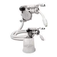
STANDARD (CLOSE COUPLED) INSTALLATION
The Cablemaster works best when the power unit is mounted directly above the stor-
age container. This will ensure proper cable extension and retraction and is recommended
providing storage space is available where hawse pipe is to be mounted (Fig. 2).
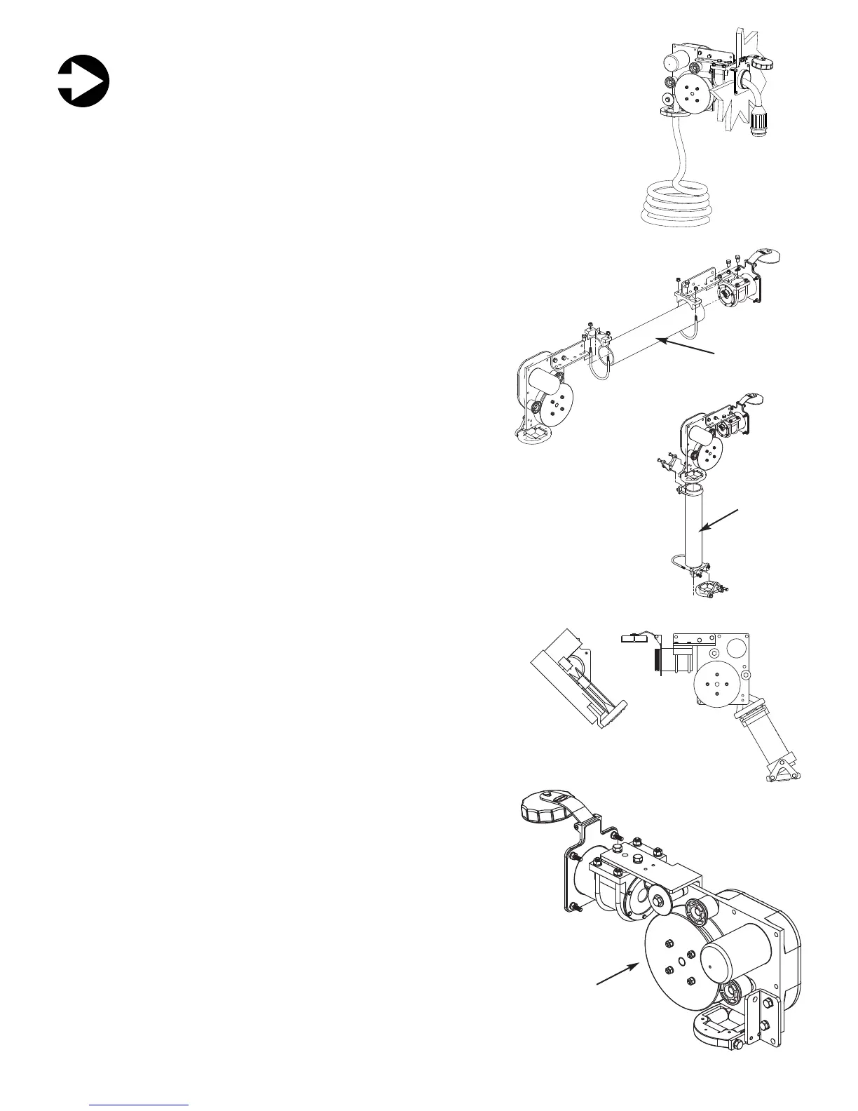
HORIZONTAL EXTENSION
When storage space is not available directly under the power unit,
the power unit can be moved away from the hawse pipe. The standard
and shortest length of the connection between the power unit and the
hawse pipe is 6 5/8”. This connection may be extended up to 16”
through the use of the optional long angle link (CM accessory). The
power unit can also be remote mounted up to 12* away from the hawse
pipe using the optional horizontal pipe extension and a length of 3”
schedule 40 PVC pipe (Fig. 3). In both of these configurations, the
power unit will require additional mounting support. An overhead mount-
ing bracket is available which allows the power unit to be remote mount-
ed to the overhead.
VERTICAL EXTENSION
Schedule 40 3” dia PVC pipe is also recommended when the shore cable is being direct-
ed vertically through the deck. In this installation it is necessary to use the optional vertical pipe
extension (see accessory page) and to remove the guide roller assembly from the power unit
and relocate it to the bottom of the pipe extension. Since this contains the out-limit switch, it is
also necessary to reconnect the out-limit switch by extending the wire to the relay box (Fig. 4).
OTHER INSTALLATION OPTIONS
Any number of mounting arrangements can be accomplished using
the PVC pipe to remote mount the power unit or guide the shore power
cable below deck. The mounting possibilities are further enhanced by the
fact that the shore power cable can be directed to the right or left of ver-
tical by adjusting the U-clamps on the hawse pipe (Fig. 5).
NOTE: A pipe to pipe angle assembly is available where a straight pipe
cannot be used between the hawse pipe and power unit. This angle con-
nector may be used in the horizontal or vertical pipe and is equipped with
rollers to provide minimal cable friction. It will work satisfactorily up to 30*
degrees (see accessory page).
NOTE: The side angle adjustment should not exceed 45 degrees and the
use of standard PVC elbows is not recommended as they tend to restrict
the movement of the cable within the pipe.
Selection of the hawse pipe location is in a large measure deter-
mined by the proper location of the power unit and cable storage area.
Be sure that the hawse pipe’s location is practical for common dockage
situations. Avoid a location where the shore power cable could present
an obstacle on decks or passageways when in use. An optional recessed
mounting bezel is available which allows the hawse pipe to be flush
mounted (see accessory page). Shown at right (Fig. 6 & 7) are other
installation possibilities for mounting the power unit and directing the
cable to the storage area.
4
B
15
Red 1
White 2
Black 3
Power
Switch
Pos. +
Neg. -
12 / 24v
DC Input
Motor
Output
CABLEMASTER RELAY ASSEMBLY
# 04034 (12, 24 volt DC)
12v DC use 20 amp breaker
24v DC use 5 amp breaker
OUT OUT
Limit
SwitchSwitch
(Remote - RED)
(Remote - BLACK)
Orange
Black
GLENDINNING MARINE PRODUCTS, INC.
Conway, SC 843-399-6146
4 4
5 5
6
7
IN
Limit
Switch
(Rmt - Green or Tan)
(Rmt - Yellow or Purple)
ORANGE
BLACK
OFF
OUT
IN
POWER
SWITCH
RED
WHITE
BLACK
IN-LIMIT
SWITCH
OUT-LIMIT
SWITCH
M
12!or!24v
MOTOR
BATERY!
POSITIVE!(+)
BATTERY!
NEGATIVE!(-)
WHITE
RED
BLACK
CABLEMASTER WIRING DIAGRAM
L
Figure 2
Horizontal
Extension
CM-7 & CM-8
WIRING DIAGRAM
RELAY ASSEMBLY
Vertical
Extension
Figure 4
Figure 5
Figure 6
Figure 7
Figure 3
1
2
3
4
5
6
IN-LIMIT
SWITCH
OUT-LIMIT
SWITCH
BAT TERY POSITIVE (+)
BAT TERY NEGATIVE (-)
GREEN
YELLOW
BROWN
BLUE
BLACK
RED
CIRCUIT BREAKER SPECS. :
CM4 - 12 VOLT 10 AMP BREAKER 4 - 5 RUNNING AMPS
BLACK
WHITE
DC MOTOR
BROWN
OUT
GREEN
POWER
SWITCH
IN
BLACK RED
YELLOWBLUE
CM-4
WIRING DIAGRAM
BARRIER STRIP ASSEMBLY
Power unit is turned
for a low-profile
configuration
 Loading...