CABLEMASTER WIRING INSTRUCTIONS (see wiring diagram, page 15)
Some wiring instructions are basic to the wiring of the Cablemaster regardless what model (CM-4, CM-7
or CM-8) you purchased.
FIRST, all wiring should be done in accordance with the instructions contained in the National Electrical Code. If there
is any uncertainty as to the proper methods of wiring, a qualified and competent electrician should do the wiring.
SECOND, overcurrent protection (fuse or circuit breaker) must be provided in the power supply to the Cablemaster. On
12v DC systems, a 20 amp fuse or circuit breaker should be used; on 24v DC systems, a 15 amp fuse or circuit breaker
is required. In addition to providing electrical “overload” protection, a separate breaker for the Cablemaster allows the unit
to be turned “off” thus preventing the unauthorized use
of the unit when left unattended. This is especially
IMPORTANT if the switch is located where it can easily be
actuated by children.
Follow the instructions below for the specific model
you purchased:
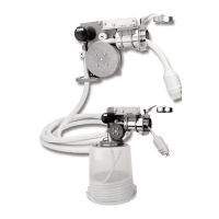
THE CM-4 POWER UNIT is wired through a barrier
strip.
All electrical connections to the barrier strip have
been completed at the factory to make for easy instal-
lation. All that is required by the installer is to attach the
battery to the appropriate terminals on the barrier strip.
Using 12 gauge, stranded wire, the positive DC power supply is connected to the #5 terminal on the barrier strip and
the negative to the #6 terminal (see drawing right). Be sure to observe proper polarity when connecting the DC input wires.
Both the limit switches are designed to automatically stop the motor when the cable has reached its’ limit of travel. The
in-limit switch is located in the hawse pipe gasket ring and is covered by a neoprene cover to shield it from moisture. The
in-limit swithch, which is connected to the #1 and #2 terminals on the barrier strip, is activated when the plug cover touch-
es the switch.
The out-limit switch, which is connected to the #3 and #4 terminals of the barrier strip, is located in the guide roller
assembly mounted on the lower side of the power unit and is activated by a nylon safety collar secured near the terminal
end of the shore power cable. The collar, which acts as a positive mechanical “stop” as well as a means to activate the
out-limit switches, should be fitted around the shore power cable at a point that allows adequate slack in the cable for
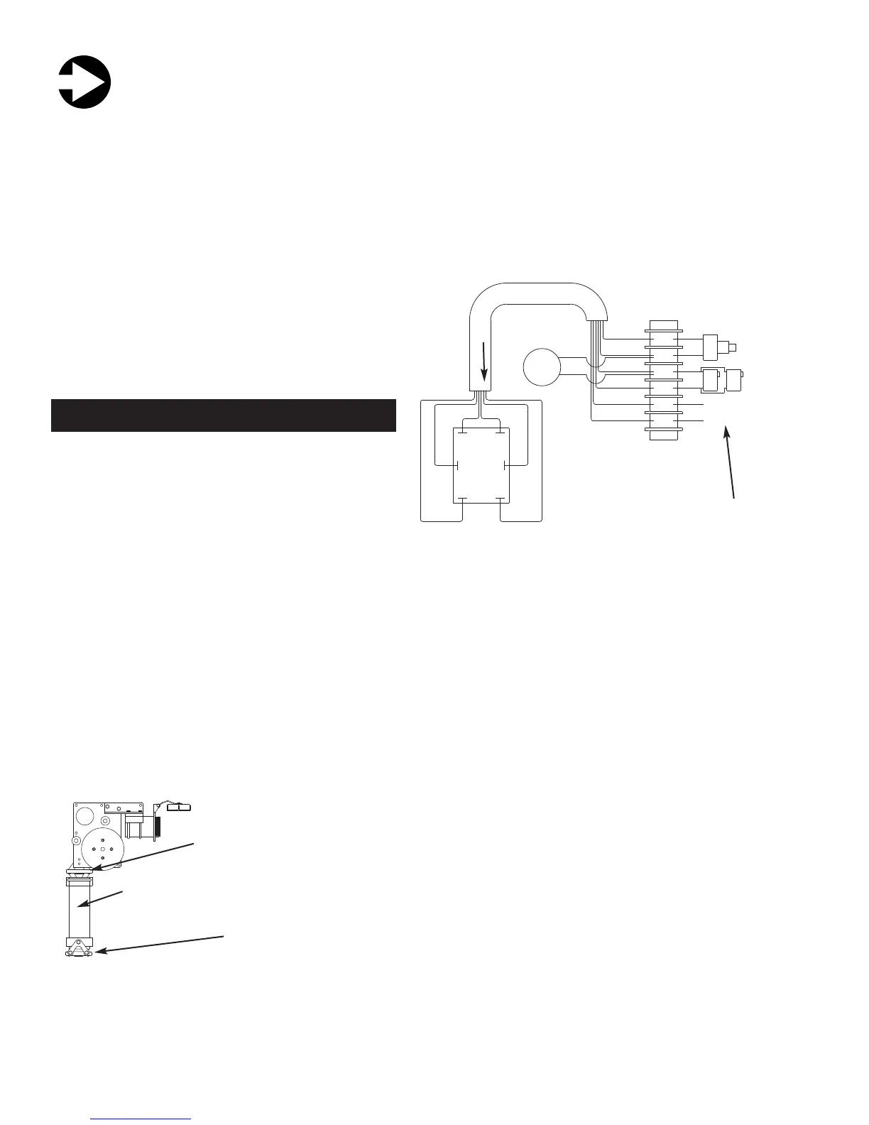
unstrained AC electrical connections. If the shore power cable is being
directed through the vertical pipe extension, it is necessary to relocate the
guide roller assembly with the out-limit switch from the power unit to the
lower end of the vertical pipe and to reconnect the out-limit switch using the
appropriate lengths of wire.
(NOTE: Failure to install the nylon safety collar and rewire the out-limit
switch can result in damage to the shore power cable’s electrical con-
nection.)
The six conductor cable for the power switch is numerically marked to cor-
respond with the numbers on the barrier strip. For convenience and ease of
operation, the power switch should be mounted near the hawse pipe or in the appropriate hole with the optional bezel. In
each case, the power switch must be protected by the neoprene cover to prevent the intrusion of moisture.
D
1
2
3
4
5
6
IN-LIMIT
SWITCH
OUT-LIMIT
SWITCH
BAT TERY POSITIVE (+)
BAT TERY NEGATIVE (-)
GREEN
YELLOW
BROWN
BLUE
BLACK
RED
CIRCUIT BREAKER SPECS. :
CM4 - 12 VOLT 10 AMP BREAKER 4 - 5 RUNNING AMPS
BLACK
WHITE
DC MOTOR
BROWN
OUT
GREEN
POWER
SWITCH
IN
BLACK RED
YELLOWBLUE
TYPICAL CM-4 BARRIER STRIP WIRING
6
Installer needs only to attach
battery power to barrier strip
WIRING THE CM-4 CABLEMASTER
MOTOR
25-5/8"
(651 mm)
Minimum distance to
center of storage space
14-1/8"
(359 mm)
13"
(330 mm)
6" (152 mm) 7" (178 mm)
28-1/4"
(718 mm)
12-3/4"
(324 mm)
8-1/2" (216 mm)
18" (457 mm)
5-1/2" (140 mm)
8-3/8"
(213 mm)
4"
(102 mm)
SPECIFICATIONS
Voltage: 12v DC (24v DC available).
Current: 7 - 11 Amps under load
Weight: 40 lbs. (Power unit)
12 lbs. (Hawse pipe)
Cable size: up to 2 gauge - 5 conductor, 100amp
Adjustable (1.325" - 1.650" dia.)
Length capacity: Determined by size of storage
location
Material: 6061 Aluminum
Finish: Power Unit: Gold Anodize
Hawse Pipe: Gold or Clear Anodize
CM-8 DIMENSIONS
Vertical
Extension
kit
NEW postion for
Out-limit switch /
Guide Roller
Assembly
Out-limit switch /
Guide Roller
Assembly normal
position
 Loading...