Glentek Inc. 208 Standard Street, El Segundo, California 90245, U.S.A. (310) 322
SMA7130, SMA71075 and SMA71100 MANUAL
For drives brought into use in Europe, use of the correct filter is essential to meet emission
requirements. Detailed information on filters is included in the manual and transformers should
be used where specified in the manual.
AC Line Filter Selection
Selection of the proper filter is only the first step in reducing conducted emissions. Correct filter
installation is crucial to achieving both EMIL attenuation and to ensure safety. All of the following
guidelines should be met for effective filter use.
The filter should be mounted to a grounded conductive surface.
The filter must be mounted close to the drive-input terminals, particularly with higher frequency
emissions (5-30 MHz). If the distance exceeds 600mm (2 feet), a strap should be used to
connect the drive and filter, rather than a wire.
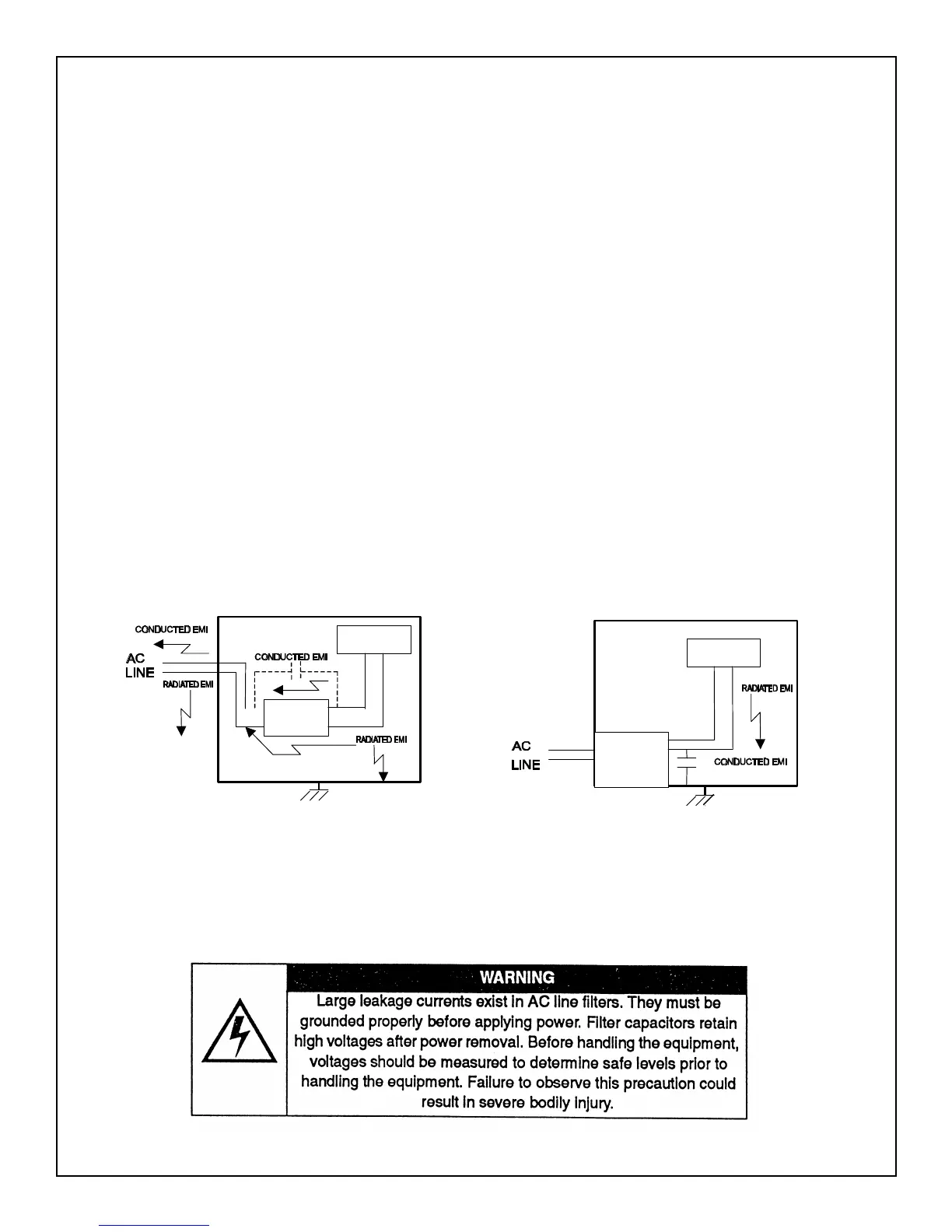
The wires connecting the AC source to the filter should be shielded from, or at least separated
from the wires (or strap) that connects the drive to the filter. If the connections are not segregated
from each other, then the EMI on the drive side of the filter can couple over to the source side of
the filter, thereby reducing, or eliminating the filter effectiveness. The coupling mechanism can be
radiation, or stray capacitance between the wires. The best method of achieving this is to mount
the filter where the AC power enters the enclosure. “AC Line Filter Installation” shows a good
installation and a poor installation.
Figure 2- AC Line Filter Installation
When multiple power cables enter an enclosure, an unfiltered line can contaminate a filtered line
external to the enclosure. Therefore, all lines must be filtered to be effective. The situation is
similar to a leaky boat. All the holes must be plugged to prevent sinking
DRIVE
FILTER
DRIVE
FILTER
APPENDIX C: EUROPEAN UNION EMC DIRECTIVE


 To Next Page