Glentek Inc. 208 Standard Street, El Segundo, California 90245, U.S.A. (310) 322
SMA7130, SMA71075 and SMA71100 MANUAL
If the filter is mounted excessively far from the drive, it may be necessary to mount it to a
grounded conductive surface, such as the enclosure, to establish a high frequency (HF)
connection to that surface. To achieve the HF ground, direct contact between the mounting
surface and the filter must be achieved. This may require removal of paint or other insulating
material from the cabinet or panel.
The only reasonable filtering at the drive output terminals is the use of inductance. Capacitors
would slow the output switching and deteriorate the drive performance. A common mode choke
can be used to reduce the HF voltage at the drive output. This will reduce emission coupling
through the drive back to the AC line. However, the motor cable still carries a large HF voltage
and current. Therefore, it is very important to segregate the motor cable from the AC power
cable. More information on cable shielding and segregation is contained in the section on
shielding.
Grounding
High frequency (HF) grounding is different from safety grounding. A long wire is sufficient for a
safety ground, but is completely ineffective as a HF ground due to the wire inductance. As a rule
of thumb, a wire has an inductance of 8 nH/in regardless of diameter. At low frequencies it acts
as constant impedance, at intermediate frequencies as an inductor, and at high frequencies as
an antenna. The use of ground straps is a better alternative to wires. However the length to width
ratio must be 5:1, or better yet 3:1, to remain a good high frequency connection.
The ground system’s primary purpose is to function as a return current path. It is commonly
thought of as an equipotential circuit reference point, but different locations in a ground system
may be at different potentials. This is due to the return current flowing through the ground
systems finite impedance. In a sense, ground systems are the sewer systems of electronics and
as such are sometimes neglected.
The primary objective of a high frequency ground system is to provide a well-defined path for HF
currents and to minimize the loop area of the HF current paths. It is also important to separate
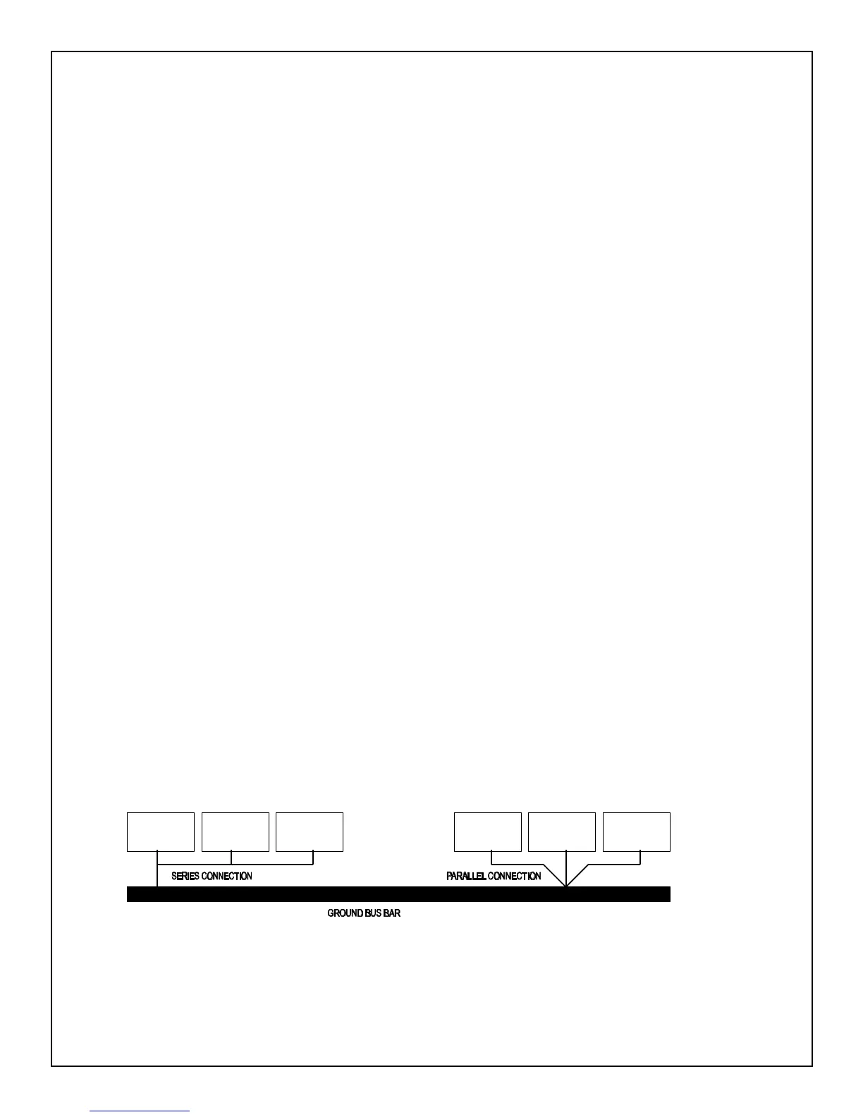
HF grounds from sensitive circuit grounds. “Single Point Ground Types” shows single point
grounds for both series (daisy chain) and parallel (separate) connections. A single point, parallel
connected ground system is recommended.
Figure
3-Single Point Ground Types
CIRCUIT
CIRCUIT
CIRCUIT
CIRCUIT
CIRCUIT
CIRCUIT
APPENDIX C: EUROPEAN UNION EMC DIRECTIVE


 To Next Page