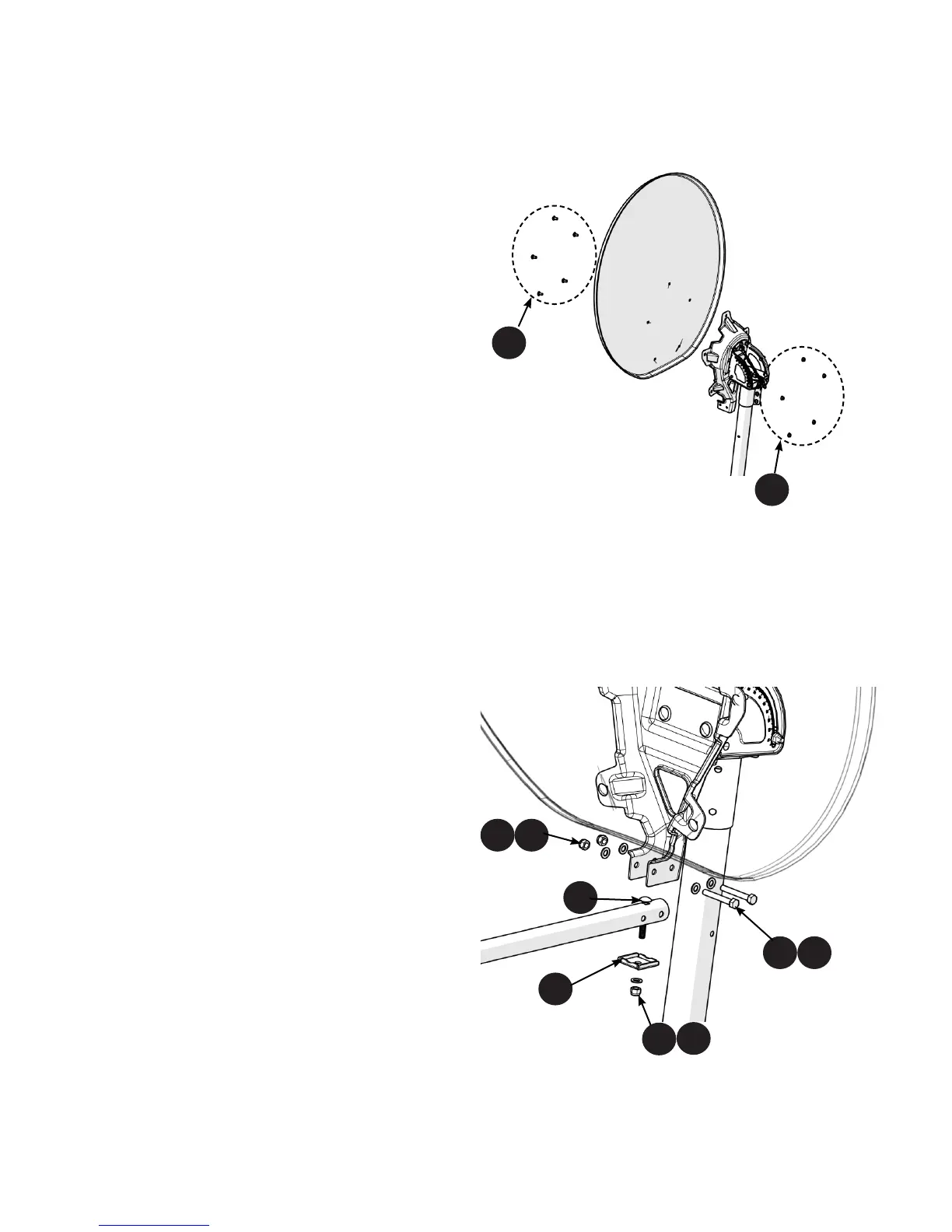
Step 4 - Aach the Feed Arm to the Back
Bracket
1. Insert one 5/16”-18 x 2-1/4” carriage bolt (Item
5/7) into the boom arm from the top.
2. Place the boom arm to align with the back
bracket holes and secure with two 5/16”-18
x 2-1/4 inch hex bolts (Item 5/3), 5/16-18 at
washer (Item 5/5) and 5/16-18 hex nylock nuts
(Item 5/4).
3. Finally, as shown here aach the boom arm
plate (Item 5/6) to the boom arm and back
bracket by aligning the 5/16-18 carriage bolt (Item
5/7)into the hole in the plate and secure using
at washer (Item 5/5) and 5/16-18 hex nylock nut
(Item 5/4).
2.0 ASSEMBLY AND INSTALLATION
4
Step 3 - Aach Reector to Back Bracket
1. Insert ve 5/16-inch x 3/4-inch carriage bolts
(Item 5/1) into the holes in the reector and through
the corresponding holes in the reector back bracket.
2. From the rear of the reector back bracket, secure
the ve carriage bolts (Item 5/1) with four 5/16-inch
hex ange nuts (Item 5/2).
3. Tighten the ve 5/16-inch hex ange nuts (Item
5/2) to 8 -lb of torque.
Note : Ensure that the carriage bolts (Item 5/1) are properly and rmly
seated before ghtening the nuts.
5/55/4
5/3
5/5
5/4
5/5
5/6
5/1
5/2
5/7