Global Power Technologies START-UP AND OPERATION
302842 Rev0 | Sentinel Page 29 of 61
4.3 SYSTEM ADJUSTMENTS
4.3.1 OPEN CIRCUIT VS POWER
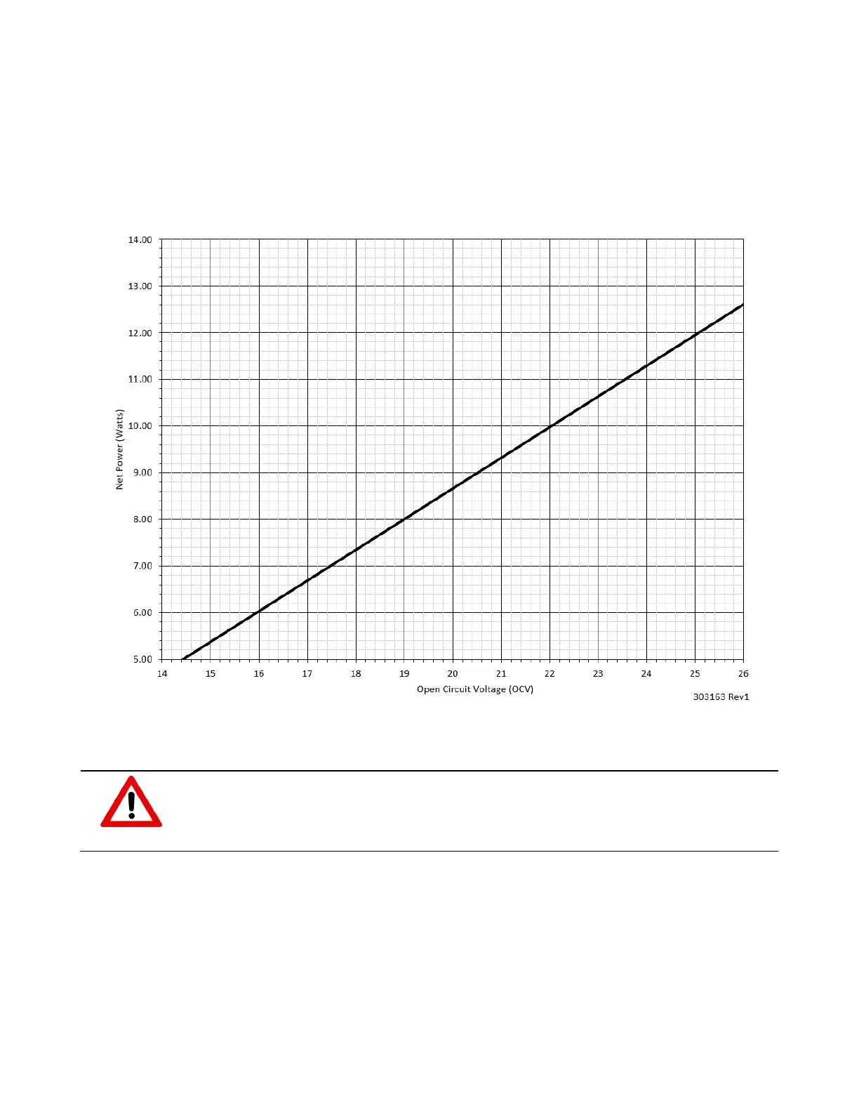
The Sentinel is configured using open circuit voltage (OCV). Open circuit voltage is the voltage
measured by the voltmeter at the sockets marked as [ + VPU – ] on the main electronics board, while
the OCV/RUN switch, SW200, is set to OCV. The following graph shows the Sentinel TEG’s net power
output in relation to the OCV.
Figure 19 – Sentinel OCV vs. Power
4.3.2 MEASURING OPEN CIRCUIT VOLTAGE
WARNING!
Ensure that no explosive gas hazard is present prior to opening the instrumentation
enclosure or servicing the Sentinel TEG. The Sentinel enclosure must not be opened
when an explosion or gas hazard may be present.
To measure the Sentinel TEG’s open circuit voltage:
1. Confirm that the SW200 toggle switch, is set to “OCV” position.
2. Insert a voltmeter into the voltage terminals (+ VPU –) located on the left side of the main
electronics board and measure the OCV.
3. Compare the OCV voltage reading to the calculated target OCV voltage—refer to Section 4.1.
4. If the measured OCV differs by more than 1 VDC from the calculated target OCV, adjust the fuel
pressure.