Do you have a question about the Global SV 550 and is the answer not in the manual?
Details the advantages and applications of the SV-550 energy-saving motor.
Lists and describes the included parts of the SV-550 motor system.
Instructions for fixing the motor bracket and aligning pulleys for the SV-550.
Steps for drilling holes, fixing the control box, and connecting cables.
Guidance on correct mounting and angle adjustment for the pedal rod.
Procedure for connecting the control box to a 220V power supply with earth.
Steps to set needle UP/DOWN positions using the disk and photo sensor.
How to adjust speed, needle positioning, and rotation direction in operator mode.
Access and adjust advanced parameters like synchronizer, speed, and torque settings.
Procedure to reset all parameters to default factory settings.
Charts detailing speed ranges based on Z and L parameter settings.
Table showing the correspondence between actual and display alphabet characters.
Diagnose and resolve common operational issues including display, motor, speed, and automatic stops.
The SV-550 is an energy-saving industrial sewing machine brushless motor designed to replace traditional clutch motors. It offers several advantages, including low friction, reduced noise and vibration levels, and a lower temperature rise during operation, contributing to a longer working life. Its compact dimensions and lighter weight also make it a practical alternative. The motor is a brushless permanent magnet type, utilizing a neodymium magnet in its rotor, which is the strongest magnet material available. This design allows for a small volume while delivering high power, making it energy-efficient and environmentally friendly, ensuring steady and reliable performance.
The device's primary function is to power industrial sewing machines, specifically light and medium-weight single-needle lockstitch machines, light-weight double-needle lockstitch machines, and heavy-duty overlock and interlock sewing machines. Its design focuses on energy efficiency, capable of saving approximately 71% energy compared to traditional clutch motors.
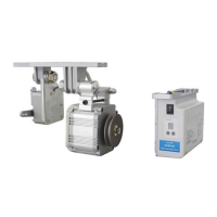
The SV-550 system comprises a motor module, a control box, and a pedal, along with a manual and an optional external synchronizer for needle positioning.
Installation of the motor module involves fixing three bracket screws into reserved holes on the sewing machine table, then securing the motor under the table with its bracket. Proper alignment of the motor pulley and machine pulley is crucial. The V-belt tension needs to be adjusted so that pressing the belt with one kilogram of force results in a concave deflection of 1.5 cm. Once adjusted, the V-belt cover is mounted, and the connecting bolts between the motor and bracket are tightened.
The control box is installed by drilling two holes (3 mm diameter, 1 cm deep, with a hole pitch of 195 mm) on the right front side under the table, then fixing the control box firmly with supplied screws. The motor plugs (two of them), the synchro plug (if applicable), and the speed control unit plug are inserted into their corresponding sockets. Cables should be bound together and secured away from the V-belt to prevent damage.
The pedal rod must be mounted vertically between the pedal and the speed control unit. The pedal's angle should be adjusted to 15 degrees relative to the ground.
For system power connection, the control box's power cord is connected to a 220 Volt single-phase power supply with a separate earth device, ensuring safe grounding. All plugs for the motor, speed control unit, and optional synchronizer should be inserted, checking that pins are not pulled back. Plug covers are then adjusted to protect the connections.
Setting the needle positions is required if a synchronizer is used (parameter M = 1). For the Needle DOWN position, the handwheel is rotated until the needle is in the lowest position. Then, the Needle DOWN disk is rotated until the gap in the disk aligns with the photo sensor. The same process applies to the Needle UP position, where the handwheel is rotated until the needle is in the highest position, and the Needle UP disk is adjusted accordingly. If the motor is used without a synchronizer (parameter M = 0), this step can be skipped.
The control box features a display that indicates the rotation direction: a dot signifies lockstitch rotation, while no dot indicates chainstitch rotation. There are two parameter levels: operator level P and technician level F.
At the operator level P, parameters can be selected by pressing the P button. These include:
To access the technician level F, the S button is pressed, followed by pressing the P button for 3 seconds until "F" appears on the display. Parameters at this level include:
A parameter reset can be performed in normal mode (P.) by pressing the S button for 3 seconds until the display shows "O" then "K" (OK).
Maximum speed settings are configured using parameters Z and L. For Z=0, the speed range (RPM) varies from 1500 to 6000 depending on the L setting (0-9). For Z=1, the speed range is higher, from 2500 to 7000 RPM, also depending on the L setting. These ranges are further adjustable by parameter V at the operator level.
The manual provides troubleshooting steps for common issues.
For general control box malfunctions, pressing the S button for 3 seconds in normal mode will reset it, indicated by "O" then "K" on the display. After the reset, the device can be re-attempted.
Environmental requirements for the device include keeping it away from high magnetic fields and radiation, operating within a temperature range of 5-45 °C, avoiding proximity to heat sources, humid environments, corrosive liquids, and explosive substances. Good ventilation for the control box and motor is essential for heat dissipation, and a stable power input voltage and reliable earthing device for the system are also required.
| Category | Industrial Equipment |
|---|---|
| Frequency | 50 Hz |
| Power Output | 550 kVA |
| Voltage | 400 V |
| Phase | 3 |
| Engine Type | Diesel |