18
0020008153A
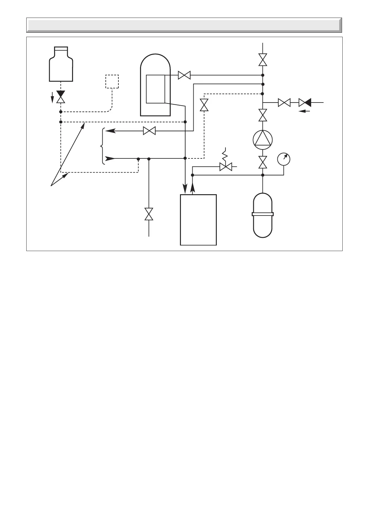
4 Water System
Diagram 4.3
9236
3 LITRES (0.66 gals)
MAKE-UP BOTTLE
(if required)
NON-RETURN
VALVE
AUTO
AIR
VENT
FLOW
DRAIN
COCK
BOILER
SAFETY
VALVE
(Make-up
alternatives)
EXPANSION
VESSEL
PRESSURE
GAUGE
CIRCULATING
PUMP
FILLING POINT
AIR
RELEASE
POINT
HEATING
CIRCUIT
BY-PASS
VALVE 'B'
IF REQUIRED
FLOW
CONTROL
VALVE 'A'
FLOW
CONTROL
VALVE 'A'
RETURN
4.5 Bypass
A bypass is not required on the central heating system unless
the system controls could allow the boiler and pump to operate
when there is no flow.
Where a bypass has to be fitted, the bypass must be placed at
least 1.5 metres away from the boiler.
4.6 Water Treatment
In the case of an existing installation, it is ESSENTIAL that prior
to installing the new boiler the system is thoroughly flushed. For
optimum performance after installation of a new system, the
boiler and its associated central heating system should also be
flushed. Flushing should be carried out in accordance with
BS7593: 1992 using a cleanser such as Sentinel X300 or X400,
or Fernox Superfloc.
For long-term corrosion protection, after flushing, an inhibitor
suitable for stainless steel exchangers should be used, refer to
the current issue of BS 5449 and BS 7593 on the use of
inhibitors in central heating systems. Examples are Sentinel
X100 and Fernox.
4.7 Open (Vented) Water System
The boiler must be supplied from an unrestricted water supply
taken from a feed and expansion cistern situated at a maximum
height of 27 metres (90ft) above the boiler.
The cold feed must be 15mm minimum size.
The vent must rise continuously and be unrestricted.
It is important that the relative positions of the pump, cold feed
and open vent are as shown in diagram 4.2.
4.8 Combined Feed and Vent
For combined feed and vent, a 22mm pipe must be fitted in
accordance with BS 5449.
4.9 Domestic Hot Water Cylinder
SINGLE FEED INDIRECT CYLINDERS ARE NOT SUITABLE
The domestic hot water cylinder must be of the double feed fully
indirect coil type.
 Loading...