17
0020008153A
4 Water System
4.1 Draining Tap
A draining tap must be provided at the lowest point of the
system, which will allow the entire system and hot water system
to be drained.
Draining taps shall be to the current issue of BS 2879.
4.2 Safety Valve
A safety valve need not be fitted to an open-vented system.
4.3 Pump
The pump should be fitted on the flow pipe from the boiler and
have isolating valves each side.
A variable duty pump should be set to give a temperature
difference of no greater than 20
0
C between the flow and return,
with the thermostat set at “MAX”, which is about 80
0
C, to give
a flow rate as shown in table 3.
See chart for pressure loss of the boiler, diagram 4.1.
High resistance microbore systems may require a higher duty
pump.
4.4 Flow Rate
If it is necessary to alter the flow rate, the system can be fitted
with a lockable balancing valve in the main flow or return pipes
shown as valve “A” in diagram 4.3. The flow rate through the
boiler must not be allowed to fall below that given in Table 3.
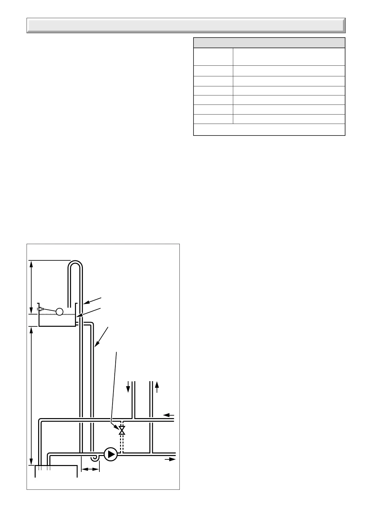
Diagram 4.2
9235
Open (vented) system.
Recommended
relationship between
pump, cold feed and vent.
22mm (MIN.) VENT
FEED AND
EXPANSION CISTERN
15mm (MIN) COLD FEED
15mm (MIN.) BY-PASS
WITH LOCKSHIELD
VALVE IF REQUIRED
RETURN
FLOW
HEATING
CYLINDER
PUMP
BOILER
150mm MAX.
1000mm
MIN.
450mm
MIN.
HEIGHT
Table 3. Flow Rate
MODEL MINIMUM FLOW RATE
12 hxi 520 litres/hr
15 hxi 646 litres/hr
18 hxi 773.8 litres/hr
24 hxi 500 litres/hr
30 hxi 1220 litres/hr
38 hxi 1633 litres/hr
This is equal to 20
o
C differential at maximum heat input.
 Loading...