46
4000123923-2
10227
CENTRAL HEATING
THERMISTOR
20 Replacement of Parts
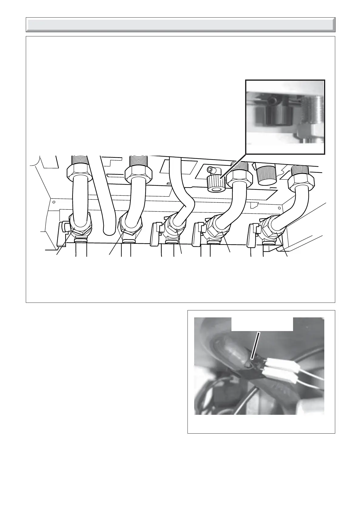
Diagram 20.2
Diagram 20.1
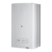
To Drain the central heating circuit
• Open drain valve fitted at the lowest point in the system.
• Allow air into the system by opening a radiator bleed screw or the boilers drain
valve (f).
(30ci Only) To Drain the Domestic hot water circuit
• Close boiler isolating valve (d).
• Turn on one or more hot water taps.
To Drain the boiler
• Close isolating screws on the isolating valves (a), (d) and (e).
• Open the boiler drain valve (f).
30ci shown
Note: Isolating cocks water and gas are shown in the: OFF position30ci shown
(f)
BOILER DRAIN VALVE
9839
(e)
(d)
(a)
HEATING
RETURN
COLD WATER
INLET
(30ci Only)
HEATING
FLOW
DOMESTIC HOT
WATER OUTLET
(30ci Only)
GAS
SERVICE
COCK
11933
(c)
(b)
IMPORTANT INFORMATION
WARNING: Before commencing the replacement of any
component, isolate appliance from electrical supply and turn
off gas at service cock.
Replacement of parts must be carried out by a competent
person.
When replacing components it may be necessary to renew
sealing washers, gaskets and 'O' rings. If new ones are
supplied with replacement components they must be used.
All parts are replaced in reverse order to removal.
If any gas-carrying components are disturbed, removed or
replaced it will be necessary on completion of assembly to
test for gas soundness and purge in accordance with the
current issue of BS6891 or in IE, the current edition of I.S.813
"Domestic Gas Installations".
20.1 Central heating thermistor
Before starting refer to the front of Section 20 Important
information.
• Remove the front panel, refer to Section 17.3.
• Lower the control panel, refer to Section 17.4.
• Locate central heating thermistor on heating flow pipe on
centre of boiler, see diagram 20.2.
• Unclip thermistor from pipe.
• Disconnect electrical connections from thermistor.
• Fit electrical connections to replacement thermistor and fit
thermistor to pipe. The polarity is not important.
 Loading...