25
221469B
11 Commissioning
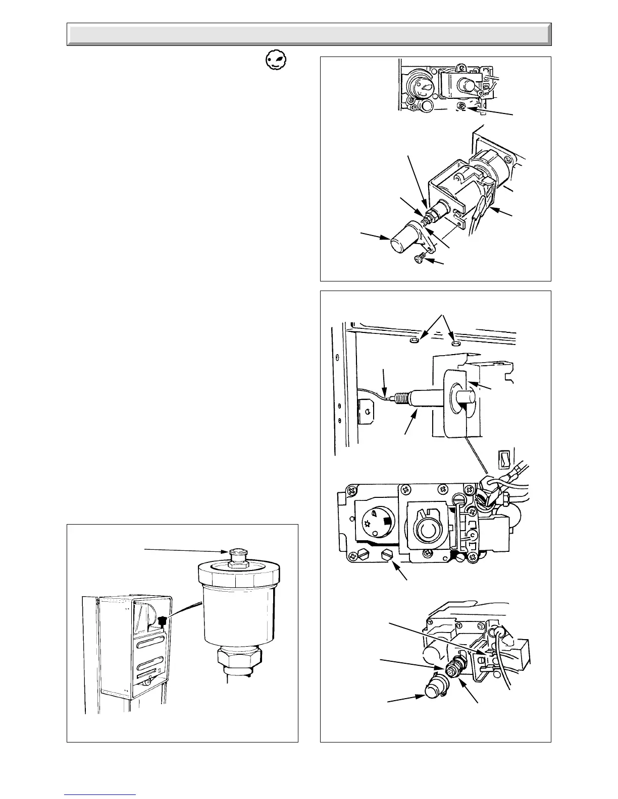
Diagram 11.3
SIT
Diagram 11.2
Diagram 11.3
HONEYWELL
SECURING SCREWS (2)
Slacken but do not remove
CAP
IGNITION
LEAD
PIEZO
UNIT
2932
CAP
SPINDLE
SMALL
ADJUSTMENT
NUT (MAX.
PRESSURE)
2344
AUTOMATIC AIR
VENT CAP
4447 S
TEST
POINT
LARGE
ADJUSTING
NUT (MIN.
PRESSURE)
ELECTRICAL
CONNECTOR
(GREY)
SCREW
PIEZO UNIT
BRACKET
Slide forward
and lower to
release from
keyhole fixing
ELECTRICAL
CONNECTOR
(GREY)
WHITE ADJUSTER
SCREW
(MIN PRESSURE)
LARGE ADJUSTING
NUT (MAX PRESSURE)
TEST
POINT
11.4 Initial Lighting of Pilot - Honeywell
Identify the boiler controls, see diagram 11.1.
Check that the boiler is isolated from the electrical supply at the
external isolator.
Fully depress and hold in gas control knob “D”.
Press and release piezo button “E” until the pilot burner lights,
(at this stage, air may be present in the gas components of the
boiler, therefore this operation may need to be repeated). When
the pilot flame has lit and is stable, keep knob “D” fully depressed
for 15 seconds, then release. The pilot burner should then
remain alight.
If the pilot flame goes out now or at any time, a safety device
prevents immediate relighting. Wait four minutes before
attempting to relight.
If the pilot burner goes out on releasing knob “D”, repeat the
above lighting sequence but this time keep knob “D” depressed
for a little longer.
The pilot flame size is preset and should envelop the
thermocouple, the approximate flame size is shown in diagram
11.4. If the flame size is incorrect refer to the adjusting
instructions in “Pilot Burner” in “Replacement of Parts” section
of the Servicing Instructions.
Check for gas soundness of the pilot supply using leak detection
fluid. Take care not to splash any of the electrical components.
Test the operation of the thermocouple flame failure system to
ensure the boiler shuts down within 60 seconds, indicated by a
“click” from the gas valve.
If the pilot burner will not stay alight, refer to “Thermocouple and
Overheat Cutoff” in “Fault Finding” section of the Servicing
Instructions.
Fit the cover of the inner case, making sure that it is fitted and
seals correctly, using the four screws previously removed, see
diagram 6.2.
Make sure that all hot water draw off taps are closed then set
switch “C” to “Off” as shown in diagram 11.1.
With the boiler isolated from the electrical supply the pilot flame
may go out. If this should happen, wait 4 minutes then relight
the pilot burner following the above lighting instructions but with
the electrical supply connected.
 Loading...


