34
221469B
3 Fault Finding
(N)
br
b
LN
(L)
PERMANENT
LIVE
240V~50Hz
OPTIONAL
SWITCHED LIVE
FROM ROOM
STAT. 240V~50Hz
b
br
v
r
PUMP
FAN
TRANSFORMER
b
br
240V~
LOW
VOLT.
24V~
LOW
VOLT.
6V~
CONTROL BOARD
CONTROL BOARD
TERMINALS, BLOCK 3
CONTROL BOARD
TERMINALS, BLOCK 2
CONTROL BOARD
TERMINALS, BLOCK 6
T1-6A
FUSE 1
3
6
2
3 3
2
2
2
2
2
2
MAINS
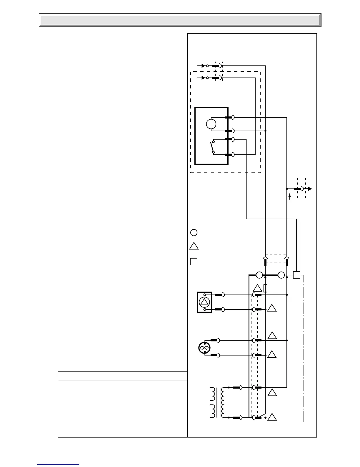
FUNCTIONAL FLOW
KEY
BROWN........................br
BLUE............................b
RED..............................r
PURPLE.......................p
VIOLET.........................v
MAINS
FUNCTIONAL FLOW
M
COMMON
ON
(N)
(L)
CLOCK/TIMER
br
b
y
br
y
6
Diagram 3.5
5718
3.4 Clock/Timer
If the clock has failed it can be bypassed by disconnecting the
plug at the wall frame. Gain access to the control box, refer to
Section 4.12, disconnect the clock wiring harness from the four
way terminal block. Fit yellow link between terminals Y1 and
Y2.
This is a temporary measure and the clock should be repaired
or replaced as soon as possible.
3.5 Electrical
The preliminary electrical system checks, as described in a
multimeter test book, are the first checks to be carried out during
a fault finding procedure.
On completion of a fault finding task that has required the
disconnection and making of electrical connections, then checks
for earth continuity, polarity and resistance to earth must be
carried out.
Isolate the boiler from the electrical supply, refer to Section 1.3.
Gain access to the boiler controls by removing the outer case,
refer to Section 1.4. Check that all cables and connectors are
secure.
Gain access to the control board, refer to Section 4.13. Check
all cables at the multi-pin connectors on the board.
Test the two fuses on the control board and renew as necessary.
Fuse 1 is type T1.6A, fuse 2 type T 630mA. If a fuse repeatedly
fails or the initial fault finding checks, described in Section 3.1
indicate a boiler fault, check the boiler electrical circuits and
follow the fault finding procedures, see diagram 3.5, 3.6, 3.7 and
3.8, and for clock/timer fault finding diagram 3.9.
 Loading...


