10
221966B
The installation of the boiler must comply with the requirements
of the current issue of BS6798.
It is recommended that plastic pipes for primary pipework
should not be used for this boiler.
3.1 Frost Protection
If the position of the boiler is such that it may be vulnerable to
freezing it should be protected as specified in the current issue
of BS5422. It is recommended that a frost protection thermostat
be fitted.
3.2 Pump
The pump, with integral valves, should be fitted in the heating
flow pipework from the boiler, it should be set to produce a
temperature difference of 11
o
C (20
o
), between the flow and
return, with the control thermostat set at “MAX”, which is about
82
o
C (180
o
F).
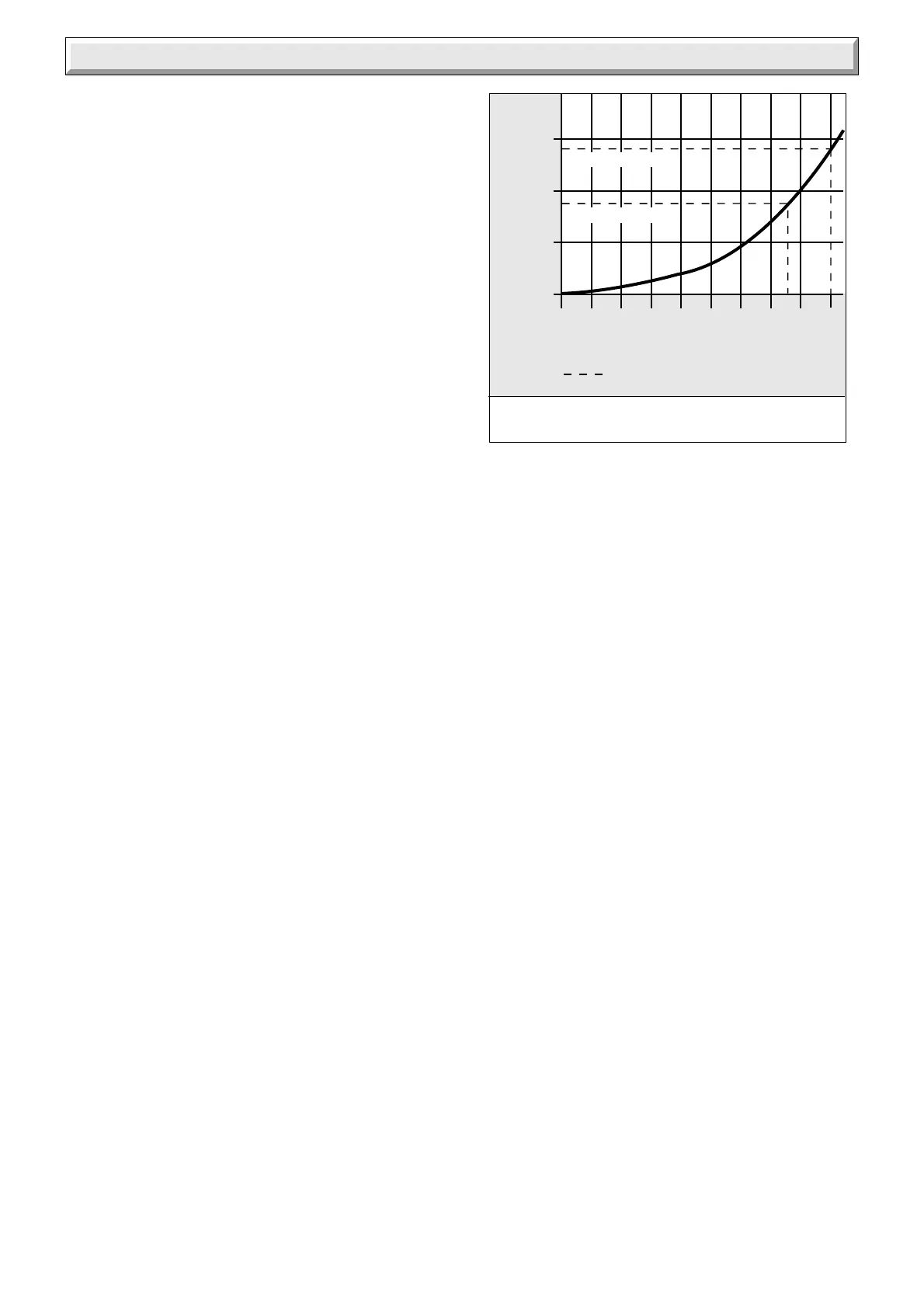
The pressure loss of the boiler can be found from diagram 3.1.
High resistance microbore systems may require a higher duty
pump.
3.3 Bypass - Fully Pumped and Sealed Water
System
A bypass MUST be fitted to a fully pumped and sealed water
system.
Where the water system allows the boiler and pump to operate
on bypass only, the bypass connection must be at least 2.5metres
away from the boiler.
The flow through the boiler must not be allowed to fall such that
there is a temperature difference greater than 20
o
C between the
flow and return.
3.4 Water System
For an open vented system the boiler must be supplied from an
unrestricted water supply taken from a feed and expansion
cistern fitted at a maximum height of 27metres above the boiler.
The cold feed must be 15mm minimum size.
It is important that the relative positions of the pump, cold feed
and open vent are as shown in diagram 3.2.
The unrestricted open vent from the boiler must rise continuously
to over the feed and expansion cistern.
3.5 Domestic Hot Water System
General. The domestic hot water service must be in accordance
with the current issue of BS5546, refer also to the current issue
of BS6700.
3.6 Indirect Cylinder
For all systems supplying domestic hot water the cylinder must
be indirect. It is recommended that the indirect cylinder be fitted
with some form of temperature control.
3.7 Fully Pumped Heating and Domestic Hot
Water
The connections for this type of system MUST be as shown in
diagram 3.2 and 3.3.
3.8 Inhibitor
Attention is drawn to the current issue of BS5449 and BS7593
on the use of inhibitors in central heating systems.
If an inhibitor is to be used, contact a manufacturer or Hepworth
Heating Ltd., for their recommendations as to the best product
to use.
When installing in an existing system take special care to drain
the entire system, including the radiators, then thoroughly
cleaning out before installing the boiler whether or not adding an
inhibitor.
3.9 Sealed Water Systems
The installation should comply with the appropriate requirements
of the current issue of BS4814, BS5449, BS6759, BS6798 and
BS7074 Part 1 and 2, see diagram 3.4 for a suggested layout.
3.10 Safety Valve
A safety valve must be fitted to a sealed water system.
It shall be preset, nonadjustable with a lift pressure of 3bar,
incorporating seating of resilient material, a test device and a
connection for drain.
The drain from the safety valve must be routed clear of any
electrical fittings and positioned so that any discharge can be
seen.
Diagram 3.1
Flow rate (litres/minute)
Water pressure loss
(mm head of water)
PRESSURE LOSS
OF BOILER 100FF/120FF
Design Flow Rate
0088(z)M
750
500
250
0
0 5 10 15 20 25 30 35 40 45
700mm (120FF)
450mm (100FF)
3 Water Systems