14
Diagram 6.1
13647
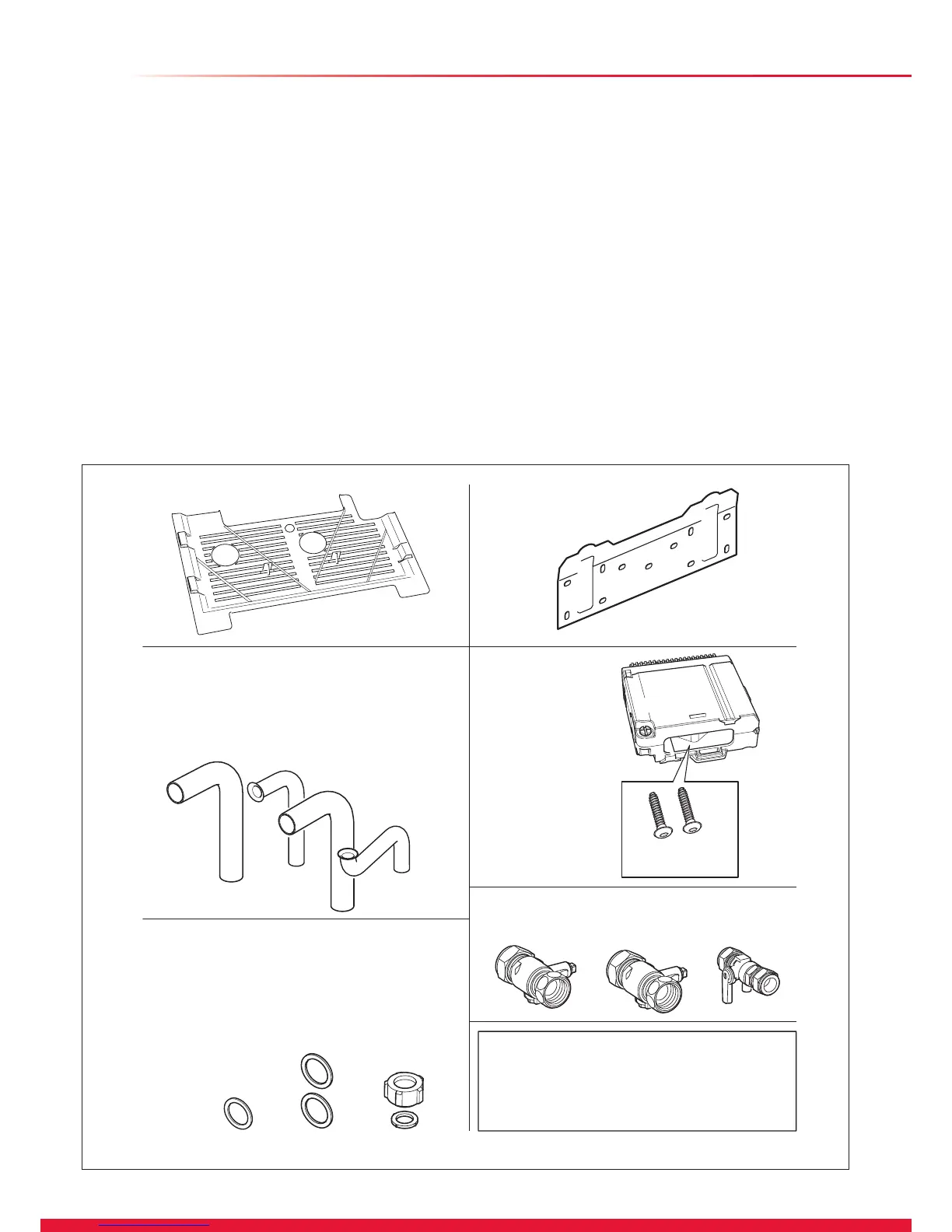
6.1 Appliance Pack
Please check the contents of packs as shown in diagram 6.1.
The packs are located in the top polystyrene packing.
Remove the carton sleeve and top pack then lift the boiler and
its polystyrene base support out of the lower pack.
6.2 Site Requirements
The boiler mounting wall should be suitable for the weight of
the appliance and be true and at.
NOTE: Due to the varied site conditions we do not supply
xings and advise that the installer should supply those which
are suitable.
6 Installation Preparation
6.3 Wall Template
Take the wall template from the document pack located within
the top polystyrene packing and place in the desired position
on the wall, giving due consideration to the required boiler
clearances, see section 3, and the ue you are tting.
Mark the position of the ue centre, if tting a side ue, extend
the ue centre line into the corner then 176mm along the
adjacent wall, see diagram 6.2.
For extended side ues, the ue hole centre should be
determined by extending the dashed inclined line on the
template to the side wall. This dashed line is drawn at 44mm/
metre (2.5°) rise from the boiler. Where this line reaches the
side wall, a horizontal line should be marked. The vertical
centre line of the ue should then be marked at 156mm from
the back wall.
To allow for the ue passing through the wall at this angle
a 125mm hole should be drilled irrespective of internal or
external installation.
Remove the wall template whilst drilling the ue hole.
B - Union Nut and Sealing Washer
A - Central Heating x 2
B - Gas
A - Large Sealing Washers
C - Gas
C - Saftey Discharge
Electrical
Cartridge
Gas and Water Isolating Valves
0020036801
Pipe Pack 0020029672
Loose Items Pack
(discard addtional items
within this pack)
A
A
A
C
B
B
Documentation Pack
(not illustrated)
Wall Template, User Instructions,
Installation and Servicing Instructions.
Hanging Bracket
C
Retaining Screws
Stored in cartridge
Base Coverplate

 Loading...


