15
Diagram 7.1
13490
6 Installation Preparation
7.1 Hanging Bracket Fixing
The Wall Hanging Bracket is supplied in the main boiler
packaging at the rear of the boiler.
Reposition the wall template over the ue hole and mark
the position of the xing holes for the hanging bracket, see
diagram 7.1.
Drill xing holes and insert suitable wall plugs.
Diagram 7.2
13479
7.2 Boiler Hanging
IMPORTANT: With regards to the Manual Handling
Operations, 1992 Regulations, the following lift operation
exceeds the recommended weight for a one man lift, refer to
section 17 Manual Handling.
Lifting the boiler into position, lean the top of the boiler slightly
to the wall and position just above the hanging bracket. Lower
the boiler slowly and engage onto the hanging bracket, see
diagram 7.2.
7 Boiler Fixing
13853
Diagram 6.2
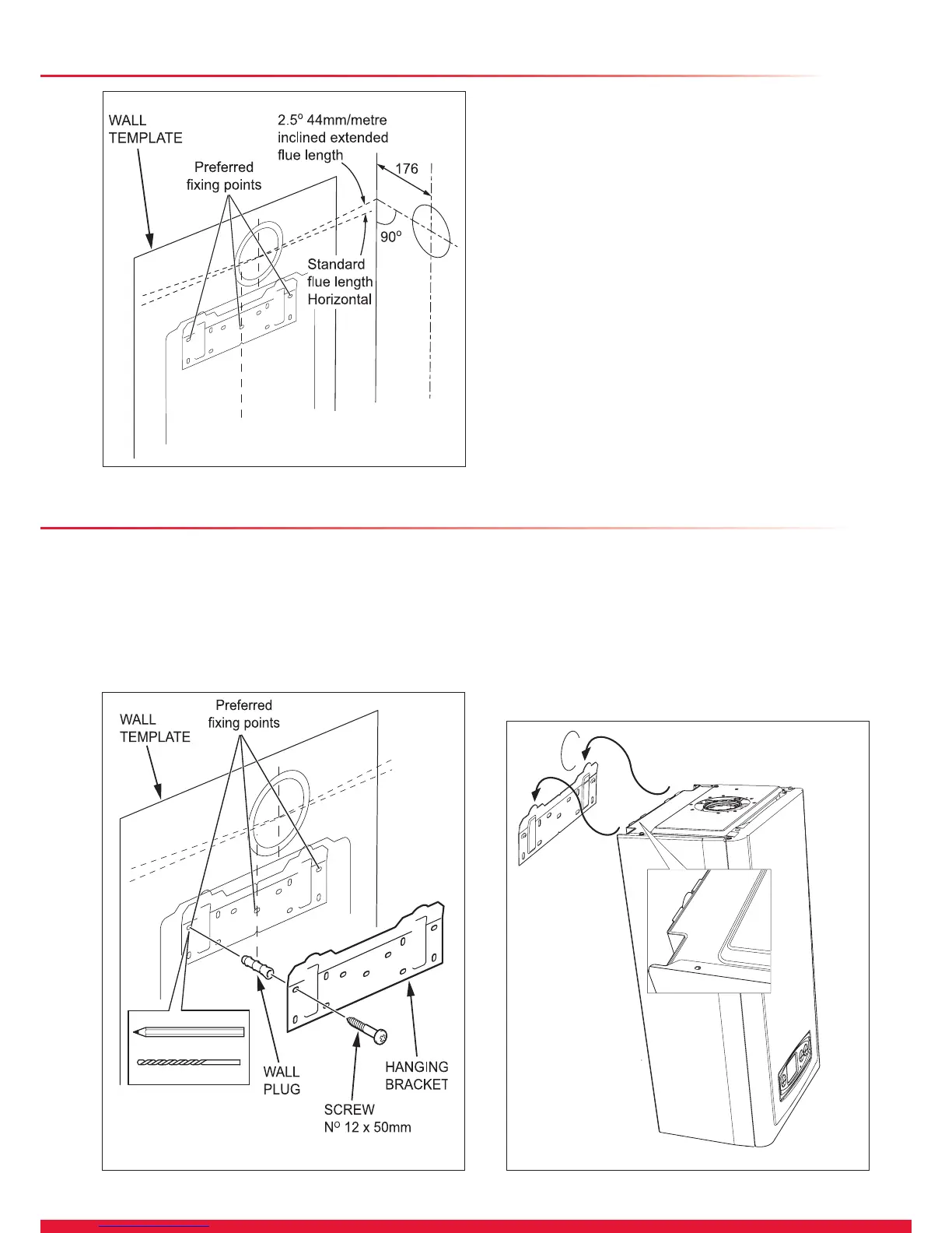
6.4 Flue Hole Cutting
External access ue installation can use a 105mm diameter
core drill.
Internal access only ue installation will need a 125mm
diameter core drill.
NOTE: The ue is designed with an internal fall of 44mm/
metre (2.5°), therefore the hole can be drilled horizontally.
If ue extension pipes are to be used then a core drill size of
125mm is required. This will allow the extension pieces to
slope at 44mm/metre (2.5°) towards the boiler.

 Loading...


